| SYSTEM OVERVIEW |
|
History
In November 2013 I received an email from Geert, owner of the "museum voor bejaarde computers". He had seen on my website that
I had built a "blinkenlight console" with a real HP1000 21MX panel. He asked whether I would be interested in a complete
HP1000 with 7906 disk drive in an HP cabinet. Of course, I am interested! He was wondering about that, because he had always
thought that I was only collecting PDP-11 stuff. "No", I wrote, I also have a Data General NOVA 3 which I picked up long ago.
"Ahh, I did not know that", he said. "Yeah, and I know that you have an Eclipse with a very nice looking tape drive".
"Do you want that?" "Oh yes, definitely!" "Come and get it, parts of the Eclipse are spoken for, but the tape drive is yours".
Early February 2014, I rented a trailer and hauled the HP1000 (that will be another story ...) and some Data General goodies.
Besides the tape drive (model not yet known), Geert also had a Dasher D200 terminal with the original blue keyboard, and the
tape controller card he had pulled from the Eclipse. It remains to be seen whether that controller can be used in the NOVA 3.
So far, so good. Now it was time to have a look at the Data General system that I hauled a "few years ago", and since then had been stored in a corner. As I did not have any knowledge of this machine, I let it stay untouched, waiting until I had learned more about the hardware. I searched for Data General information and found out that there is not much out there! I decided to write a web page about everything I will learn about the NOVA 3 and its peripherals, and started looking in my old emails for information of this NOVA 3 ... I found it and it was much longer ago than I thought! How time flies ...!
Edward had sent me an email back in December 2005 (!) that he had seen a Data General NOVA 3 on a Dutch auction site. The auction
title was "Data General Nova 3d", and the pictures already showed that this was not something like the size of a desktop PC.
At that time, I still had some room space left, so I wrote the seller that I was interested. Frans Smits, the seller, replied
that he had seen my website, and that he was confident that "his" system would go to a good home. He was the first owner of this
NOVA 3, and he had bought the machine 20+ years ago for some 100,000 (1980) Guilders, over 50,000 Euro nowadays. On that machine
he developed programs written in COBOL for his company. He sold large canisters of paint to many car repair companies in Belgium
and Holland in the region Antwerpen - Rotterdam. Payroll, address information, stock, orders etc. was processed and stored on the
NOVA 3. I had to promise to erase all customer-related data. Besides the NOVA 3 in a 6-foot cabinet, Frans also had one Data
General terminal and a printer without keyboard. I hauled the system, together with several boxes with documentation and disk
cartridges in the first week of January 2006.
Time went by ... The NOVA 3 silently awaited being powered up again ...
8 years later ... I got an email from Geert. The rest is not history, no, it forced me to start digging in
the "Data General world".
Links to other sites
Jumps within this page are the following.
General NOVA 3 system information
The NOVA 3 is known by a few other names, but these names all refer to the same type of system. Other names are
The processor of the NOVA 3 is a single, large (15" x 15") circuit board which goes into slot #1. Looking at the front console of
the machine, the opening of the system card cage is at the right-hand side, and slot #1 is the lowest slot of the backplane.
The NOVA 3 officially can support 128 KW (256 KB) according to Data General, but can really handle up to 256 KW (512KB) with a
single-word patch to the RDOS operating system. The NOVA 3 was the last NOVA with "real lights and switches" and signaled the end
of an era for Data General.
more to be added ...
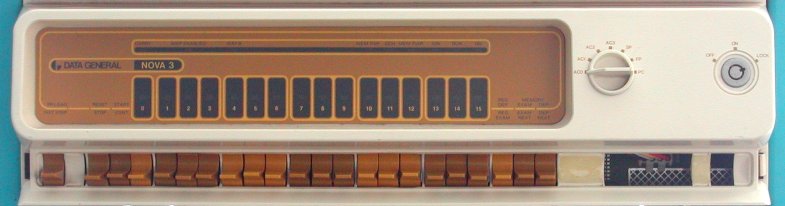
The state of the machine is shown on two rows of indicator lights and can be modified with a row of switches
on the bottom section of the console.
At the right-hand side of the console is one rotary switch with 7 positions and the
OFF/ON/LOCK key switch.
| rotary switch | explanation |
|---|---|
| AC0 | REG DEP and REG EXAM operate on accumulator 0 |
| AC1 | REG DEP and REG EXAM operate on accumulator 1 |
| AC2 | REG DEP and REG EXAM operate on accumulator 2 |
| AC3 | REG DEP and REG EXAM operate on accumulator 3 |
| SP | REG DEP and REG EXAM operate on the stack pointer (SP) |
| FP | REG DEP and REG EXAM operate on the frame pointer (FP) |
| PC | REG DEP and REG EXAM operate on the program counter (PC) |
When the REG DEP switch is lifted the contents of the data switches is stored into the register indicated set by the current setting of the rotary switch. As long as the switch is lifted, the value set by the switches is displayed in the DATA indicators. When the switch is released, the contents of the PC is displayed. When the REG EXAM switch is pushed the contents of the register indicated set by the current setting of the rotary switch is displayed in the DATA indicators. When the switch is released, the contents of the PC is displayed.
In the top section are the following indicators (from left to right).
| indicator | explanation |
|---|---|
| CARRY | Indicates the state of the carry bit in the ALU. |
| MAP ENABLED | One of the two program maps is enabled and not inhibited, or a data channel map is mapping addresses. |
| MAP B | Program map "B" or data channel "B" is enabled. |
| MEM PAR | The memory parity feature has detected a memory error. |
| DCH | Indicates that the next processor cycle will be used by the data channel for direct access to memory by an in-out device. |
| MEM PWR | Power is supplied to the semiconductor memories. |
| ION | Interrupts are on, that is they are enabled, allowed to interrupt the normal instruction execution. |
| RUN | The processor is in normal operation mode, executing instructions from memory, or data is being transferred via the data channel. When the indicator is off the processor has stopped. |
| ON | 5V power is supplied to the CPU. |
In the middle section of the console are the DATA indicators numbered from left to right 0 .. 15.
This is a bit awkward, because nowadays we are all used to see the least significant bit at the right side, indicated by "0".
The 16 indicators show the current contents of the PC unless an operator panel is being performed.
In the lower section are the following toggle switches (from left to right).
| switch | action | explanation |
|---|---|---|
| PR LOAD - - - - - - - INST STEP | momentary up momentary down |
Lifting the toggle "up" specifies the PROGRAM LOAD action. Starts the (optional) internal bootstrap
loader. Pushing the toggle "down" specifies the INSTRUCTION STEP action. Every time this toggle is pushed, the processors executes one instruction. The contents of the selected register (by the rotary switch) is displayed in the DATA indicators, and the machine state is displayed in the indicators in the upper section. EXAM can be used to load the PC before beginning any single step procedure. Instruction stepping can also be done by pressing START while holding STOP pushed down. |
| RESET - - - - - - - STOP | momentary up momentary down |
Lifting the toggle "up" specifies the RESET action. The processor is stopped after completing the
current processor cycle, and an I/O RESET instruction is executed. The Interrupt On flag, the 16-bit priority mask, and all Busy
and Done flags are cleared. Pushing the toggle "down" specifies the STOP action. The processor leaves the RUN state after the current instruction execution is completed and before executing the next instruction. If an I/O device requests an interrupt during the execution of the current instruction, it is honored before the CPU is stopped. Data channel requests are honored while the machine is in the stopped state. After the CPU is stopped, the DATA indicators show the address of the next instruction to be executed. The STOP state can be changed to the RUN state by pressing the CONT toggle. |
| START - - - - - - - CONT | momentary up momentary down |
Lifting the toggle "up" specifies the START action. The data set by the 15 switches (1 ~ 15) is stored
in the PC, a reset is sent to the I/O bus, and the processor enters the RUN state. Pushing the toggle "down" specifies the CONTINUE action. This causes the processor to resume execution after an executed HALT instruction, or a manually pressed STOP toggle. |
| 0 ~ 15 | up down |
16 data switches to enter an address or set data to be stored. Switch in the "up" position represents a "1". switch in the "down" position represents a "0". |
| REG DEP - - - - - - - REG EXAM | momentary up momentary down |
Lifting the toggle "up" specifies the REGISTER DEPOSIT action. The data set by the 16 switches is stored in
the register specified by the rotary switch. As long as the switch is held in the "up" position, the value set by the 16 switches is
displayed in the DATA indicators. When the switch is released, the PC is displayed in the DATA indicators. Pushing the toggle "down" specifies the REGISTER EXAMINE action. The contents of the register specified by the rotary switch is shown in the DATA indicators. As long as the switch is held in the "down" position, the value is displayed in the DATA indicators. When the switch is released, the PC is displayed in the DATA indicators. |
| EXAM - - - - - - - EXAM NEXT | momentary up momentary down |
Lifting the toggle "up" specifies the EXAMINE action. The PC is loaded with address set by the 15 switches
(1 ~ 15) and the contents of the memory location indicated by the PC is displayed in the DATA indicators. Pushing the toggle "down" specifies the EXAMINE NEXT action. The PC is incremented by 1, and the contents of the memory location indicated by the (incremented) PC is displayed in the DATA indicators. As long as the switch is held in the "up" or "down" position, the value in the memory location is displayed in the DATA indicators. When the switch is released, the PC is displayed in the DATA indicators. |
| DEP - - - - - - - DEP NEXT | momentary up momentary down |
Lifting the toggle "up" specifies the DEPOSIT action. The data set by the 16 switches is stored in
the memory location specified by the PC. The PC is set by a previous EXAM action. Pushing the toggle "down" specifies the DEPOSIT NEXT action. This is the same as the DEP action, but first the PC is incremented by 1 before the data set by the 16 switches is stored. As long as the switch is held in the "up" or "down" position, the value set by the 16 switches is displayed in the DATA indicators. When the switch is released, the PC is displayed in the DATA indicators. |
This NOVA 3 system configuration
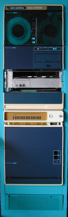
This NOVA 3 system is housed in a standard 6-foot high cabinet.
In the lower part of the rack, under the NOVA 3 chassis, is an empty space of 5.25" high and below that is a
Above the NOVA 3 chassis is again 5.25" high empty space and then the
Above the model 6031 diskette drive is again some empty space, and then, behind a blind panel, is another "half-height" unit. That unit is an expansion box and has a power supply in the bottom part, and a 4-slot backplane. In the first slot (the lowest slot) is one module installed. At the front side of the module (where the levers are to pull the board out of the card cage), is in one corner the text "8 LINE ASYNC MUX" in the etch, and in the other corner is the number 10700046404 in the etch. So, this is a communications chassis that can contain multiple multiplexer cards (multi-line serial port controllers). I plan to move that expansion unit between the NOVA 3 chassis and the model 6031 diskette drive, so that a full-height space comes available to mount the model 6125 tape drive that I got from Geert.
Update
Forgot to take pictures of the system in its original state. In the picture you can see that the communications chassis is moved between
the model 6031 diskette drive unit and the NOVA 3 box. In the top free space of the cabinet I installed the model 6125 tape drive.
Looks great ![]()
This is a list of the boards installed in the CPU box. Note that the bottom slot is number one, and contains the NOVA 3 processor.
| slot | identification | part number |
|---|---|---|
| 12 | FDISK CONTROLLER | 005-8927 |
| 11 | DISK CONTROLLER | 005-3982 |
| 10 | COMM. BASIC I/O | 005-8096 |
| 9 | DGC NOVA CASSETTE I/O | 005-3552 |
| 8 | <empty> | |
| 7 | <empty> | |
| 6 | DGC NOVA3 16K MEMORY | 005-5962 |
| 5 | DGC SC MEMORY | 005-7789 |
| 4 | DGC NOVA CASSETTE I/O | 005-3552 |
| 3 | DGC SC MEMORY | 005-7789 |
| 2 | TRIPLE OPTION | 005-7843 |
| 1 | NOVA 3 CPU | ? |
The "DGC NOVA CASSETTE I/O" boards most likely have a serial port interface on them and the "cassette I/O" section is probably not populated. This 4075/76/77/78 controller was favored over the standard Data General 4007/8/9/10 serial port controller as it had more options and was easier to configure than the 4007 board.
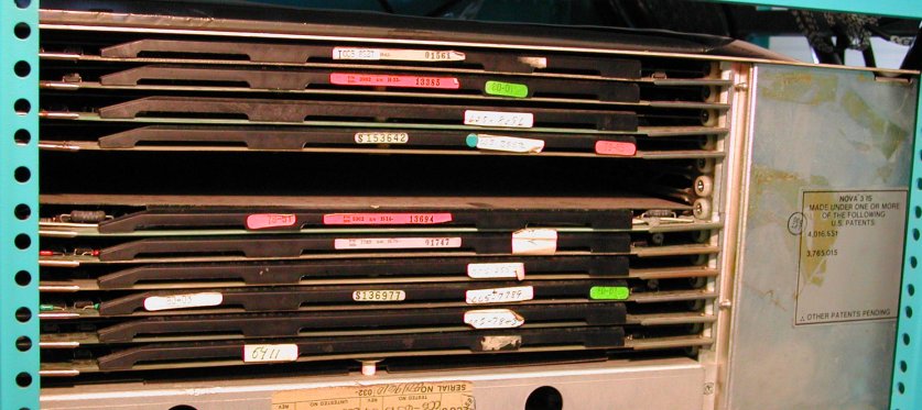
The boards slide into the box from the right side. To install a board, you just pull the CPU box on its slide forward out of the
cabinet. Then you can install a board in an enpty slot. Basically, that is all. See the picture. This is how my CPU box right side
looks as I got the machine. I do not know whether there should be a closing metal cover - in that case it is missing
![]()
At the left side of the CPU box is the rear side of the backplane in which all boards are plugged. The pins of the connectors are some 15 mm long and if "something" must be connected to the module (for example console wires or a device interface cable) you need the approriate cable with a header that can be plugged onto the correct pins. It is clear that the correct connection cable and relevant documentation are a necessity! ... and that can be a problem; in fact two problems. The cable is probably difficult to find, especially if you do not know the part number, and the relevant documentation (which may tell what cable you need) is also difficult to find.
|
On the rear side of the CPU box is a label. Obviously, the number 6070 relates to the hard disk drive, and the number 6031
relates to the floppy disk drive. Peter Simpson, who used to work at Data General, explained this to me. The label at the back of the CPU enclosure with the model numbers and slot numbers are the options that originally came with the system when it was first shipped. The P2, P13 and P15 are Interrupt Priority numbers. |
|
more to be added ...