A floppy disk interface for the RealConsole
Introduction
This page describes the project to add a floppy disk drive interface to the Core Board.
The design is set up in such a way that, without any major changes, you can connect all the standard drives to this
controller (8", 5Ľ", and 3˝" drives). However, if I want the big stuff (8" drives) I turn on a real PDP-11,
so I built and tested the hardware only with two 3˝" drives. As far as I know, you can connect 5Ľ" drives without any
modification. If you do want to connect 8" drives, you must remove one of the two 0,1 µF capacitors of the
PUMP circuit at pin 23 of the 2793 floppy disk controller, and change the source code accordingly to
set a few bits in the Floppy Control output port.
Here are a few links to jump quickly forward on this page.
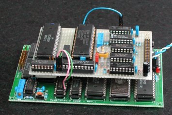
Construction
 The floppy disk controller needs most of the signals common to all peripherals on the Core Board. Instead of soldering
a lot of wires to the Core Board (ugly!), I use the signals on the 6821 PIA. The PIA is removed from the socket (you did
put your 6821 in a socket, did you?), and another socket is plugged into that socket on the Core Board. That socket is
soldered to a wire-wrap socket which is soldered to the "piggy-back" board. The piggy-back board has the 6821 and all the
components to connect to the floppy disk drives.
The floppy disk controller needs most of the signals common to all peripherals on the Core Board. Instead of soldering
a lot of wires to the Core Board (ugly!), I use the signals on the 6821 PIA. The PIA is removed from the socket (you did
put your 6821 in a socket, did you?), and another socket is plugged into that socket on the Core Board. That socket is
soldered to a wire-wrap socket which is soldered to the "piggy-back" board. The piggy-back board has the 6821 and all the
components to connect to the floppy disk drives.
There are three signals which must be connected by an "air wire" from the Core Board to the FCB (Floppy Control Board).
They are indicated red.
- CLK - the 4 MHz oscillator signal from 74LS73 #1
(or 8 MHz if you did the "performance upgrade")
- IOd* - address range $00Dx select 2793 FDC from 74LS138 #10
- IOc* - address range $00Cx select output port from 74LS138 #11
The jumpers, indicated in green, are for the following selections. Here you see the experimental character, as JP2 and the
not named double jumpers near the 74LS04 are probably not needed in the final design.
- JP1 - selection of the input clock (8 or 4 MHz)
- JP2 - (dis)connects pin #2 (DENSITY SELECT) of the floppy IDC
- JP3 - test jumper to adjust the data separator of the 2793 FDC
- JP4 - IDC connector to the floppy drive
- JP* - 2 connections (wired-OR, to be tested) to the CB1 pin of the 6821 to
» generate an interrupt when the diskette is removed
» generate an interrupt when the 2793 FDC asserts DRQ*
|
|
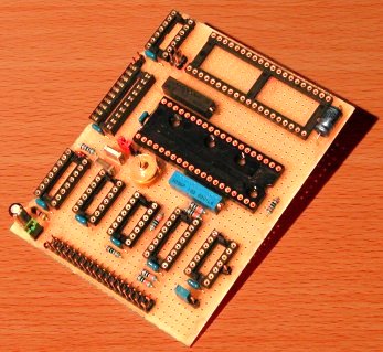
| Component side |
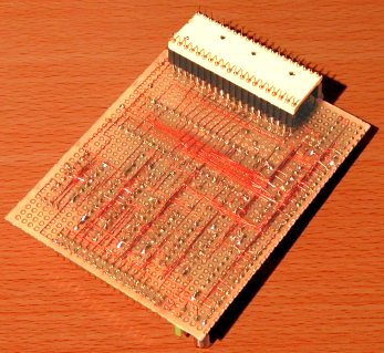
Wiring side with extension socket |
An octal output latch is used to control several signals to the drives (for example MOTOR-ON).
You could use a latch from the I/O Board but I want to design the FCB in such a way that you do not need to connect
the I/O Board. For that reason the FCB has its own output latch and the signal IOc* is needed to
latch the data written to it.
The floppy disk drive has a signal pin "Disk Changed". I would like to connect this signal to the CB1 input pin of the PIA, but
that pin can only flag a level transition. I will have to do some tests (hardware and software) if I can make this usable.
You can download the electrical diagram (72 kb, 1060x721), but
keep in mind that I did not yet check/test the DISKCHG signal. The jumper to the CB1
pin of the 6821 PIA is still open.
Modern 3˝" disk drive connection
 If you use a "PC" cable (with a twist) make sure that both floppy drives are set to the same "number", for example A.
If you make your own cable because you do not want that excessive long flat cable, it will be a "straight" cable, so
make sure that both drives are set to a different "number". Of course, if you are going to use only one drive, this does
not really matter, but you still want the connected drive to become "DRIVE #0".
If you use a "PC" cable (with a twist) make sure that both floppy drives are set to the same "number", for example A.
If you make your own cable because you do not want that excessive long flat cable, it will be a "straight" cable, so
make sure that both drives are set to a different "number". Of course, if you are going to use only one drive, this does
not really matter, but you still want the connected drive to become "DRIVE #0".
Remark. Pin #2 selects double density or high density and at the same time reduces the write current.
For this reason the signal is sometimes called "Low Current". I read that the assignment is inverted between 5Ľ" and 3˝"
drives. The modern 3˝" HD drives do not depend on this signal, but recognize the data from the floppy disk. I intend not
to use this signal. Also, I am not sure what direction the data flow is.
Remark. Pin #34 is set when there is no diskette in the drive, and stays set until explicitly cleared
by the controller. Clearing this signal will only work if a disk is in the drive, so clearing the signal and check its state
immediately can be used to probe for disk presence. A good method to clear the signal is sending the "restore" command.
Some drives update this signal slowly, so it can take some time before the signal state is actually updated.
Adjustment of the Data Separator of the 2793
To adjust the Data Separator of the 2793 you need a frequency counter and an oscilloscope ...
The 50k potentiometer connected to RPW (pin 18) sets the internal Read Data pulse, and the 60 pF trimmer
capacitor sets the frequency of the VCO. Do the following steps to align these two settings.
- During the reset keep the TEST* input (pin 22) to a logic '1' (normal state).
After the reset set the TEST* input to a logic '0' for the adjustment procedure.
- Connect an oscilloscope to the TG43 (pin 29).
Adjust the RPW pulse width with the 50k potentiometer to 250 nsec (for 8" drive, double density).
- Connect a frequency counter to DIRC* input (pin 16).
Adjust the trimmer capacitor to the appropriate data rate (500 kHz for 8", double density).
During the above described adjustments DDEN* must be kept logic '0', and
8/5* must be kept logic '1' (for 8" drive, double density), else you must double the adjustment
times above (5Ľ" or 3˝" drive, single density). So that would be 500 nsec for the RPW pulse width, and
250 kHz for the data rate. You can control the DDEN* and 8/5* either under
software control or remove the 74HCT374 latch and apply the logic levels to the 2793 yourself.
When you want to use the FDC in double density mode (DDEN* = 1), the 2793 has the capability of a
user-defined precompensation value for Write Data. The 10k potentiometer connected to WPW (pin 33) allows
a setting of 100 to 300 nsec from nominal. Do the following steps to set the Write Precompensation value.
- Force the TEST* input (pin 22) to a logic '0'.
You can see a stream of (needle) pulses on the WRITE DATA output (pin 31).
- Adjust the WPW potentiometer for the desired pulse width.
The adjustment can be made in-circuit since WRITE GATE (pin 30) is inactive while TEST*
is '0'.
Low-level driver software
The initial test software is the low-level stuff to control the output port bits to set the FDC in the correct operating
mode, and select/activate the drive. As this output port can not be read back and you must be able to change only a few bits
without changing the other bits, a "shadow" register is maintained in the software. After initialization, separate functions
change the specific bits in the FCB output port. That piece of code was easy, as the commands to move the head (restore to
track 00, step-in, step-out, and seek track). In the first code these commands work without the "verify" bit, because I do not
(yet) have a diskette with the correct format.
To read or write a sector you must write the code as compact as possible (counting intruction execution cycles), because of
timing restrictions which are as follows according the WD2973 specifications.
| mode | single density | double density |
|---|
| read | 27.5 µsec | 13.5 µsec |
| write | 23.5 µsec | 11 µsec |
|
These are worst-case figures!
The timing restrictions for a write operation are so high that it is impossible to implement double density on a 1 MHz clocked
6809 using a polling loop.
At 1 MHz, using a polling loop, it is just possible to implement single density!
|
Click the following link to get a copy of the
TMS279x data sheet
(40 pages, 335 kb) from the nice website of Michael Holley.
Before you can read or write a sector you must format the disk! The 2793 has a "format track" command, after which you
send the correct data to the disk. You can not determine all data "on the fly", because of the same timing
restrictions. So, you build a sequence of the required data stream in memory and send that prepared sequence to the FDC.
To save instruction cycles, the byte counter is not a 16-bit register, but the 8-bit [B] register, because the -1
decrement of a 16-bit register takes 4 cycles, whereas the 8-bit register decrement takes 2 cycles. For a 512 byte read operation
you simply use 2 identical loops of 256 bytes! Also, to save instruction cycles, you must make the access to the FDC registers
as fast as possible. If those registers are in zero-page use the direct addressing mode, else you can use the [DP] register
to set the FDC register addresses in "zero-page" (save & restore the original [DP] value!), or use the 16-bit registers as
pointers to the FDC status and data registers.
       ldx   #DSKBUF     ; pointer to buffer space
       ldu   #FDCsts     ; access FDC status reg through pointer
       ldy   #FDCdat     ; access FDC data reg through pointer too
       clrb              ; read 256 bytes (use 2 loops for 512 bytes)
       lda   #0x80
       sta   FDCcmd      ; issue READ_SECTOR command
                         ; # (cycle count)
                         ;---
  10$: lda   ,u          ; 4
       bita  #DRQbit     ; 2  data byte available ?
       beq   10$         ; 3  n - wait for it
       lda   ,y          ; 4  y - get data byte from FDC
       sta   ,x+         ; 6      store it in buffer
       decb              ; 2  all bytes read ?
       bne   10$         ; 3  n -
The read loop needs 24 cycles, which is ok. To write data you simply change the "lda ,y" and "sta ,x+" into "lda ,x+" and "sta ,y".
However, the timing is now not ok, in a worst-case condition you will get "LOST DATA" errors! You
could change the sequence of the data in the buffer and then substitute the "lda ,x+" with a "pulu a" 'stack' operation (set up [X]
and [U] accordingly), because the "pulu" instruction needs 5 cycles and has implicit pointer update. That would bring the write loop
down to 23 µsec but you have to admit that it is very close to the worst-case condition ...
Using an interrupt routine (where the DRQ* pin of the FDC generates the interrupt) is not an option! The IRQ
of the 6809 stacks all registers which costs too many cycles. The FIRQ of the 6809 only stacks the program counter and the condition
codes, but the (fast) interrupt routine must stack the used registers too!
However, the 6809 has an other mechanism through which you can get rid of the polling routine, the "SYNC"
instruction. You still need to connect the DRQ* pin of the 2793 FDC to either the IRQ*
or FIRQ* pin of the 6809 (it does not matter which interrupt pin you use). In software you make sure that interrupts
are not enabled! When DRQ* is asserted, the 6809 will not start the execution of the interrupt service
routine, because the interrupts (IRQ and FIRQ) are disabled. However, if the 6809 processor has executed the SYNC instruction, it
will await an "interrupt" (IRQ* or FIRQ* pin asserted), and after that event occurred continue
with the next instruction. Note. I found out that simply masking the interrupts in the 6809 CPU
is not sufficient. You must also make sure that no peripheral device (like the 6821 PIA!) asserts the interrupt hardware line to the CPU.
        ...               ; set up the pointers
        tfr   cc,a        ; get current IRQ/FIRQ state
        pshs  a
        orcc  #0x50       ; disable FIRQ and IRQ !!
        clrb              ; read 256 bytes (2 loops for 512 bytes)
        lda   #0x80
        sta   FDCcmd      ; issue READ_SECTOR command
                          ; # (cycle count)
                          ;---
   10$: sync              ; 2  await data request from FDC
        lda   ,y          ; 4  get data byte from FDC
        sta   ,x+         ; 6  store it in buffer
        decb              ; 2  all bytes read ?
        bne   10$         ; 3  n -
        puls  a
        tfr   a,cc        ; restore previous FIRQ/IRQ state
Without polling, the read loop is worst-case executed in 17 µsec, and that is also fast enough for the write loop, so there is
no need to swap the buffer and use the "pull" instruction to get rid of the auto-increment instruction.
It is clear that double density is not possible, unless you double the 6809 clock!
At the end of the "format track" operation, you can not simply use the "SYNC" construction, because you do not
exactly know how many GAP4 bytes must be written due to drive tolerances. A check is done on the "DRQ" and
the "BUSY" status bits to see if the format track operation is finished. As long as DRQ
is asserted and "BUSY" is set a GAP4 byte is written.
*EXEC 2300

testprogram for WD2793 FDC  <26dec05>

  FDC : [HIOTRW]   Home stepIn stepOut Track Read Write
  OUT : [7]...[0]  outport bit number on/off test toggle

.2793> 2  out port = 00100100
.2793> 3  out port = 00101100
.2793> T
0:::::::::0:::::::::0:::::::::0:::::::::0:::::::::0:::::::::0:::::::::0:::::::::

.2793> 3  out port = 00110100
.2793> 2  out port = 00110000
.2793>
|
I have successfully formatted track 00, but got a hung condition in the writing of GAP4. The hung was on the "SYNC"
construction, which I did not yet change into a polling loop. However, that means that the 16 sectors of 128 bytes were correctly
initialised (in single density). I can read any sector from track 00, and I get 128 bytes of $E5 (the format data pattern). I can also
write any sector in track 00, and when I read that sector back I get the previously written data. Things are looking good so far!

I replaced the "SYNC" construction with the "DRQ" / "BUSY" status bits
polling and the format track finishes without a hung, and the testcode returns to the command prompt. I 'polished' the format routine
a little, because I am going to use that code in the final "CDOS09" (short for Core DOS 6809). When a track is successfully formatted,
a "." (dot) is printed. Then the same track on the other side is formatted. When that was successfull too, the displayed dot is erased
and a ":" (double-colon) is printed, except when the written track is modulo-10 (or track 00). Then a "0" (zero) is printed instead of
the double-colon. The "bit output" to #2 and #3 are to select/deselect the drive and turn the motor on/off.
CoreDOS 6809
Now that I can format the disk and have working routines to write and read a specified sector of the floppy, I started to rewrite
the simple DOS that I wrote for my 6800 system back in 1981-1982. After 2 weeks of debugging, I have a working "DOS" with all the
commands I need to work with this small system. I wrote a small program that allowes a big text to be printed with some special
characters in the text to control the output. Xon and Xoff from the keyboard will stop the text output at the end of the current
line being printed, and control-C aborts the output. I saved that program to disk, marking it as an "executable", so that the
'run' command can show the text. After the 'save' command I changed the protection of the disk, as you can see in the screen
output from the 'directory' command. Then I made the text output program delete-protected and ran the proggie. That text is in the
screen below, and gives a summary of the implemented DOS commands.
I noticed one minor bug in the DOS code: the saved file does not have the date field filled in. I will correct that one soon!
CORESYS-09 v1.5
*EXEC 8000

CoreSYS DOS 6809  (v1.0 11jan2006)
CDOS09 ~0> dr 2
CDOS09 ~2> date 12jan06
CDOS09 ~2> label testfloppy
CDOS09 ~2> fo
           *DISK FORMAT PROTECTED*
CDOS09 ~2> fo!
           format disk - sure? Y
0:::::::::1:::::::::2:::::::::3:::::::::4:::::::::5:::::::::6:::::::::7:::::::::
CDOS09 ~2> di!
  label & date : testfloppy    12jan06   used sectors = $0000
  used directory sectors   = $0003       bad directory sectors = $00
  direct available sectors = $04F0       tot available sectors = $04F0
  disk format protected    # files = $00           bad sectors = $0000

CDOS09 ~2> sa doshlp.txt;2200:32ef!2200
CDOS09 ~2> pr<>
CDOS09 ~2> di
    name  ext   prot   typ    date     byte   load   strt
  --------------------------------------------------------
   doshlp txt   ---x                   10F0   2200   2200

  label & date : testfloppy    12jan06   used sectors = $0012
  used directory sectors   = $0004       bad directory sectors = $00
  direct available sectors = $04DE       tot available sectors = $04DE
  disk format allowed      # files = $01           bad sectors = $0000

CDOS09 ~2> pr doshlp.txt<d>
CDOS09 ~2> di
    name  ext   prot   typ    date     byte   load   strt
  --------------------------------------------------------
   doshlp txt   -d-x                   10F0   2200   2200

  label & date : testfloppy    12jan06   used sectors = $0012
  used directory sectors   = $0004       bad directory sectors = $00
  direct available sectors = $04DE       tot available sectors = $04DE
  disk format allowed      # files = $01           bad sectors = $0000

CDOS09 ~2> run doshlp.txt

* administrative commands (no disk I/O)
----------------------------------------------------------------------------
  drive #
     select a logical drive number (where number is 0,1,2,3)
     number 0 and 1 are side 0 and 1 of physical drive 0, and
     number 2 and 3 are side 0 and 1 of physical drive 1.
  date ddmmmyy
     specify a date stored when a disk is formatted (format date), and
     stored when a file is saved. The day and year is 2-digit numeric,
     the month is 3-letter abbreviation. No leap year check is done.
     When no date is set, the date on a saved file will be blank.
  date system
     this 'date' is a special case to identify system files
  label labelname
     specify a label name (max 12 characters) used when a disk is formatted
     When no label is given, the formatted disk wil have a blank label.
  help
     show a summary of the available CoreDOS09 commands
  exit
     return from CoreDOS09 to the CoreSYS monitor

 continue ...?

* disk read-only access commands
----------------------------------------------------------------------------
  get filename;load_address
     read the specified file from disk and store the data starting at
     the specified load-address (load_address is 4 hex digits).
  run filename
     read the specified file from disk. The data is stored at the address
     specified when the file was saved, and the program is started at the
     address specified when the file was saved ('x' protection required).
  direct filename
     show information about the specified file
  direct!
     show the disk status (format date, label, file count and sector info)
  direct
     show information about all files stored on the disk and disk status
  ?! track;sector:load_address
     panic read of a disk sector (diagnostic purposes)
     The 128-byte sector from the specified track and sector number is
     read from the disk and stored at the specified load-address.
     track is 2 hex digits (00-7F), sector is 2 hex digits (01-10), and
     the load_address is 4 hex digits.

 continue ...?

* disk write access commands
----------------------------------------------------------------------------
  format
     format a (new) disk
     when a disk read access fails, the disk is formatted (no confirmation)
     when the read access succeeds, the format protection is checked.
     See also the 'label' command.
  format!
     format a (new) disk
     when a disk read access fails, the disk is formatted (no confirmation)
     when the read access succeeds, the format protection is overruled,
     but a confirmation request is issued. See also the 'label' command.
  delete filename
     delete the specified file from disk if delete protection is not set.
  protect filename<p>
     set or clear the protection flag(s) for the specified file
     <d> sets the delete (format) protection flag
     <c> sets the file rename protection flag
     <>  removes all protection flags
     the delete and rename flags can be combined in one command ().
  protect<p>
     set or clear the disk format protection flag
     <d> sets the format protection flag
     <>  clears the format protection flag
  rename old_filename=new_filename
     rename (the existing) specified old file to the new file if the rename
     protection flag of the old file is not set. The new file has the same
     protection flags as the old file.
  rename old_filename=new_filename<p>
     rename (the existing) specified old file to the new file if the rename
     protection flag of the old file is not set. The protection flags of
     the new file are set or cleared as specified for the new file.
  squeeze
     defragment the disk. Files are written to disk in contiguous sectors.
     Gaps from deleted files are removed by moving all files to contiguous
     blocks.
  save filename;begin_address:end_address!start_address
  save filename<p>;begin_address:end_address!start_address
  save filename;begin_address:end_address
  save filename<p>;begin_address:end_address
     the specified file is saved to disk and has the optional specified
     protection flags. The begin-address and the end-address are mandatory
     and is specified in 4 hex digits.  The optional start-address marks
     the file as an 'executable' and the 'x' protection flag is set, so
     that the file can be used with the run command.
     See also the 'date' command.

CDOS09 ~2>
*
|
CoreDOS meets the world
With CoreDOS, I have an easy device to store and load programs on the 6809 Core Board. However, the world is PeeCee thingies.
For my pdp8/e simulator I made a program to split a file (a disk container, but that is not relevant) on the PC into small
files dumped in the Motorola S19 record format. With that program I had a clumsy method to transfer a file from the PC to
my 6809-based pdp8/e. The PC "side" is of course SIMH. So, would it not be nice if I could transfer data from the PC to the
Core Board using a floppy disk?
Yes, of course! I searched the web for some specification documents of the FAT12 file system that Microsoft uses for MS-DOS.
The hard part was that you can not find a PC nowadays that formats floppy disks in single density. The already mentioned
timing constraints are even more tight when you want to read a diskette formatted at double density (720k). But reading
a diskette at double density is possible with a 6809 clocked at 1 MHz! I added some routines to CDOS09 to read the root directory
of an MS-DOS double-density formatted floppy, and load a file from the root directory. I did not bother to implement any of the
sub-directory possibilities.
The "FAT" command in CDOS09 sets up CDOS09 to read a FAT12 double-density formatted floppy, and disables all commands that write
to the diskette, as that is not implemented. All commands that do not access the floppy are valid in "CFAT" mode, and of all other
commands that are available in "CDOS" mode, only "GET" and "DIR" are available in "CFAT" mode.
Here is a display of CDOS09 in "CFAT" mode, as I called it.
EXEC 8000

CoreSYS DOS 6809  (v2.1 - 08aug2006)
CDOS09 ~0> dr 2
CDOS09 ~2> fa
CFAT09 ~1> di
bytes/sector  = 0200   sectors/cluster = 02   reserved sectors = 01
# FAT tables  = 02     entries in root = 70   # sectors/FAT    = 03
tot # sectors = 05A0   number of sides = 02   # sectors/track  = 09
-------------------------------------------------------------------
FAT720K .      ---V--            25-JUL-2006  12:54:30
SMALL   .TXT   -----A   000019   28-JUL-2006  14:18:04
BIGFILE .TXT   -----A   000156   28-JUL-2006  14:20:22
FILE5   .      R----A   000019   28-JUL-2006  14:18:04
FILE6   .      ------   000019   28-JUL-2006  14:18:04
FILE3   .      -----A   00001B   01-AUG-2006  13:24:52
FILE4   .      -----A   00001B   01-AUG-2006  13:25:22
SUBDIR  .      ----D-   <dir>    01-AUG-2006  13:31:26

CFAT09 ~1> get BIGFILE.TXT;4000
CFAT09 ~1> di!
bytes/sector  = 0200   sectors/cluster = 02   reserved sectors = 01
# FAT tables  = 02     entries in root = 70   # sectors/FAT    = 03
tot # sectors = 05A0   number of sides = 02   # sectors/track  = 09
-------------------------------------------------------------------
CFAT09 ~1> ex
CDOS09 ~2> ex
CORESYS-09 v1.5
*
|
Note that in "CDOS" mode, there are four logical drives possible that map to 2 physical drives with 2 sides per drive. As MS-DOS
formats the diskette double-sided you only have two logical drives drives that map directly to 2 physical drives.