| Full-size console pdp8i (FPGA-based) |
Clearly, there are a few difficult components in this project.
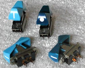
The original switches are almost "unobtanium", and then there is the issue of the art work for the pdp8i front panel face plate ...
The kick start for this project was an offer on Usenet of the switches circuit board of a PDP-15! Those switches have an identical
shape as the switches DIGITAL used on the pdp8i panel, only with a different color. The board was damaged and not complete, but
contained enough switches to construct a good pdp8i switch panel! We'll see how the project will finish ...
Vince (in the USA), John (in Australia), Hans (in France) and I (in The Netherlands) bought the Xilinx XESS XSA-3S1000 FPGA development kit which has sufficient functionality and I/O pins on board for our purpose.
| back to top |
| back to top |
The front panel assembly is probably the easiest part, at least at first glance. But it depends on your starting point. The
difficult issue here is of course obtaining the (look-alike) switches, or go with some other type of switches.
Have a look at Bob's Spare Time Gizmos pdp8 project
( SBC6120 Front Panel ) for
ideas. You might get lucky on eBay ...
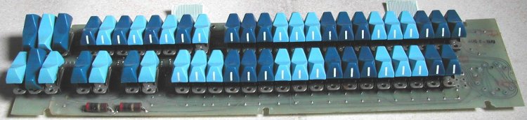
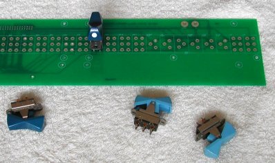
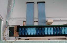
As I said, I was so lucky to buy a scrapped front panel circuit board of a PDP-15 ... believe me, if it was a complete front panel
I would have build a replica PDP-15 with the actual console and SIMH behind it. But it was missing one switch and the two
rotary switches at the right hand side. You can see in the picture that the two ribbon cables were simply cut ...
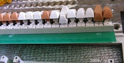
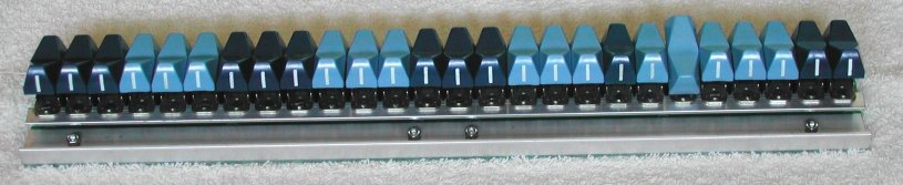
Eager to see what the new pdp8i switch panel would look like, I tried to put the desoldered switches on the circuit board of Vince. The switches have a near perfect fit, but if the pins of the switches are not completely cleaned of soldering tin remains they will not fit! I used a file to remove the last tin parts. That took quite some time, but hey, if you want to get a perfect result, you must spend some time getting things done right!
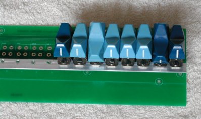
After putting some switches on the circuit board, it became obvious that, to get all switches perfectly aligned in a row, a rod was needed to mount the switches on with a small screw and nut. The real pdp8i uses a rod that is mounted on the circuit board. That was a bit too much for me, and I decided to make a strip of aluminum with holes. But there is not much space between the plastic cap of the switch and the head of a screw. So the aluminum strip is installed at the rear side of the flanges of the switches.
Note that the momentary switches (LOAD ADDR and DEP for example) are mounted slightly
slanted at one side on a real pdp8i front panel. I did not do that as my switches aligned perfectly in height, maybe the PDP-15
switches are a little different, and I liked it the way it is now.
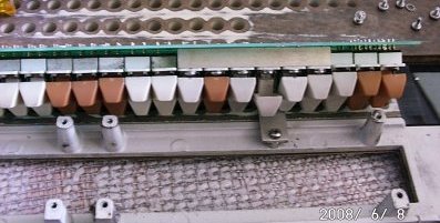
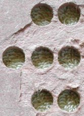
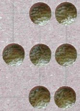
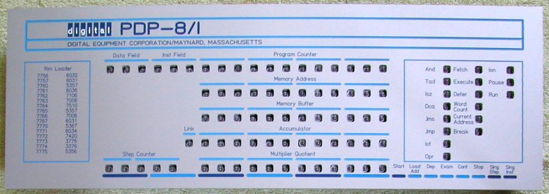
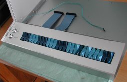
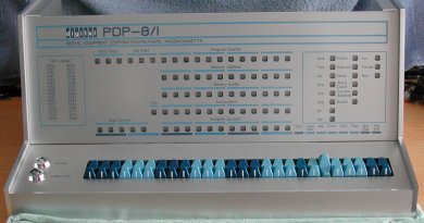
Below are two pictures Vince took of the (real) pdp8i front panel with the new replacement circuit board.
|
|
| checking that all switches fit in the holes of the circuit board | checking that all switches align in the holes of the ALU strip |
| back to top |
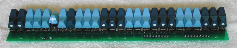
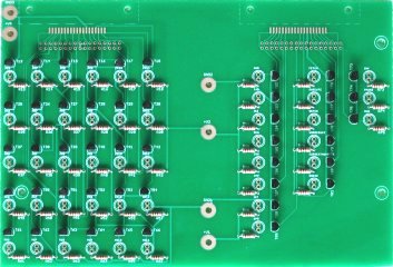
The front panel lights board is actually built on two boards. Splitting one large board into two parts is cheaper to manufacture. The board on the left side (when viewed from the font side) has the bulbs (or LEDs if you prefer) for DF0-DF2, IF0-IF2, PC0-PC5, MA0-MA5, MB0-MB5, LINK, AC0-AC5, SC0-SC4, and MQ0-MQ5. The board on the right side has the remaining bulbs for the registers and the "functional execution" indicators, like the instruction currently executed, and the pdp8 processor state.
|
|
| The two boards of the front panel lights, the 100 Ohm resistors (see text) and transistors already soldered. | |
|---|---|
 The variation from bright yellow/white to dimmed orange/red will certainly look great, and Vince found a good source
That also explains why I use a 100 Ohm resistor in the collector of the driver transistor. The power supply voltage is 12 Volt and
the bulb is rated for 8 Volt. At 40 mA, the voltage drop of 4 Volt is realized by a resistor of 100 Ohm. A nice "feature" of the
series resistor is sort of a safety measure for the transistor. If the bulb becomes defective and creates a short circuit condition,
the resistor will limit the current through the transistor. Hopefully, the resistor will die before the transistor will ...
In the real pdp8i, the bulbs are also Bi-Pins, but are soldered directly onto the light board. That is a reason why Vince developed
a drop-in replacement for the lights board of the pdp8i. Removing a dead bulb and soldering a new bulb is hard on the traces on the
original lights board, and finally the lights board becomes difficult to keep in working order. The mentioned site sells 8V Bi-Pin
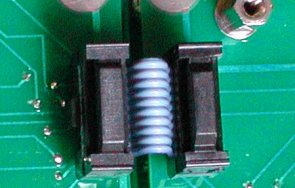
bulbs. Just do not solder the Bi-Pin bulb directly on the board, but put it in machined pins removed from an IC socket! Some
real pdp8i models also have the bulbs "socketed" instead of soldered on the circuit board.
You put the Bi-Pin bulb in two pins and then solder the two pins on the light board. The reason for using a Bi-Pin bulb to get the two pins soldered is two-fold. First, it is easier to solder. But more importantly, you can correct for the pitch difference as the holes in the light boards is slightly smaller than the distance between the two pins of the Bi-Pin bulb.
Assembly of the lights boards
As usual, the best way to solder all components on a circuit board is going from "low-profile" to the components that are higher
off from the circuit board. So, start with soldering all resistors on one circuit board. If you use bulbs with a 12 Volt rating
you can either solder low-resistance resistors or just a simple piece of wire.
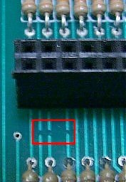
We had issues with the manufacturer of the circuit boards, and by a routine check Vince discovered that the vias are not all
reliable on the carrier board! To prevent a lot of work, I suggest to check out the circuit board after you soldered the bridge
wires or resistors. An Ohm meter or (even faster checking it out) a beeper is all you need. Since the transistors are not yet
soldered you can "poke around" as nothing can get damaged.
Do these checks on the left side lights board (if you don't want to be surprised later):
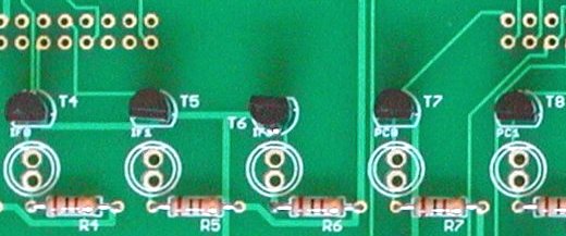 My left side lights board was 100% OK. Thanks to checking out the board, I noticed that one of the 42
transistors (T6) is mounted 180° rotated.
My left side lights board was 100% OK. Thanks to checking out the board, I noticed that one of the 42
transistors (T6) is mounted 180° rotated.
Also, solder the components neat "in line" and solder the transistors close to the circuit board.
Remember that in the final assembly, pieces of card board or a drilled mask must be put over the circuit board to shield the
lights from each other to prevent ghost stray light of a neighbor bulb.
Check very carefully which type of transistor you have.
I thought that Vince ordered 2N2222A transistors, but Jameco sells PN2222A.
These two types are very much alike, but the collector and emitter are "swapped". I found out the hard way. Vince saw my pictures
and told me. A simple check made clear that I had to remove 89 transistors from the boards to install them the other way around!
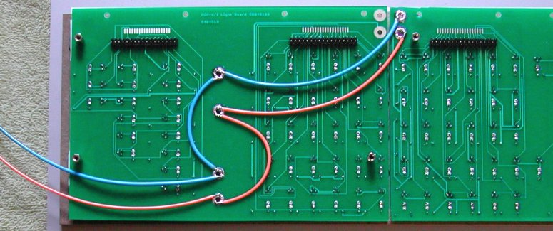
Assembly of the right side lights board is identical to the left side lights board, just 47 resistors and transistors. After soldering the resistors, check the board as described. Mine checked out 100% OK. All transistors are soldered "in line", but notice that the 3 transistor row ION - PAUSE - RUN are rotated 180° compared to the other two vertical rows at the right side.
Finally solder the two 34-pin male headers on the left side lights board and the two 34-pin male headers on the right side lights board.
Note that all 4 headers are soldered at the rear side of the boards, that is, on the
opposite side of the transistors/resistors and bulbs.
| back to top |
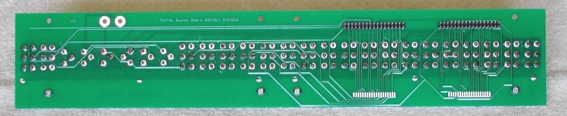
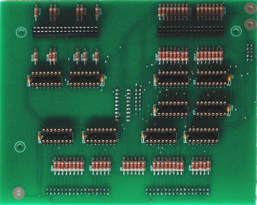
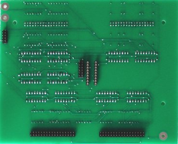
The assembly steps for the carrier boards are the same as the light boards. I started with the easier board #1, which I will call the "DeMux shift registers" board, as this board contains the shift registers to read the switches and a few of the shift registers for the lights.
|
|
| "Demux shift registers" board (component side) | "Demux shift registers" board (solder side) |
|---|
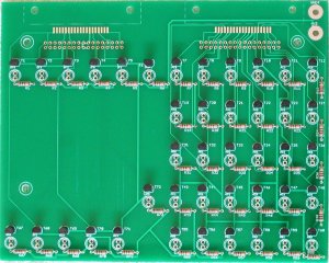
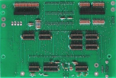
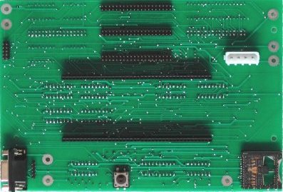
Carrier board #2 contains the carrier pins for the XESS module, the remaining shift registers for the lights and some logic. This so-called "Mux and carrier" board also contains an SD card holder (not used in the current implementation) and a MAX232A for RS-232 connection to a PC. This connection can be used for a terminal console or reader/punch teletype.
|
|
| "Mux and carrier" board (component side) | "Mux and carrier" board (solder side) |
|---|
Finally, solder all capacitors and the 3 jumper wires. These jumpers are no configuration "things" but merely
connect power supply connections with different names in the Eagle drawing. Using the jumpers prevents complaint
messages from Eagle.
| back to top |
The switches that look like the original (or are the original) are nearly unobtanium parts, but you can say the same
of the front panel from a real pdp8/i. You can try eBay or other auction sites, but chances are slim one front panel will be
up for auction. And if it is, be prepared to pay a premium price, at least $200, but more likely $300! True, you have
the original, but you must have deep pockets, and have the patience to wait until this rare item is for sale!
I started with the "lights mask", which is a wooden (or metal) plate of several millimeters thickness with holes for the
light bulbs. The lights mask must shield stray light from one bulb to the other. At first, I planned to use 9 mm thick
wood, but then I thought about the heat developed by the bulbs, and decided to go for a more expensive solution: make the
lights mask from aluminum. I started the drawing in Front Panel Express
( USA site or
European site ).
You can download the free drawing package from their site. The user interface is fairly intuitive. You start with
specifying the dimensions of the front panel and the thickness of the material. While you add items like drilled holes,
you can always look at how much the total design will cost.
After drawing the lights mask, I played around with the other possibilities of Front Panel Express ... in the end, I had
a fairly complete front panel, even with the not perfect round openings for the lights, but the sort of rounded
rectangular shape. The only thing to do is adding a frosted sheet of plastic and the finishing touch is a real glass plate
of 3 or 4 mm thickness.
The front panel for the switches is a lot easier as you can see. I used the drawing of the front panel design for the lights as a start to make sure that the switches will align with the art work on the lights panel. I have chosen not to mount the switches onto the front panel. Instead, the printed circuit board with the strength-enforcing L-shaped aluminum bar will be installed on the bottom of the housing of the complete system.
| back to top |
My front panel design has M3-threaded holes at the rear side at the exact location where the original pdp8/i lights printed circuit board has mounting holes. The 2-boards set of Vince also has these holes. There are two approaches how to build the front panel, lights boards and logic boards together. You can use simple screws and separate the boards and the boards from the front panel using bushings, cut at the correct length. I used the other approach: building the construction together "layer by layer". Starting with the rear side of the front panel, I first mount the lights boards and make sure that the bulbs fit nicely in the openings of the front panel. Then some wire soldering is needed before the logic boards are added. The "layers" are mounted at the correct distances from each other using hexagonal stand-offs which have an M3 threaded screw at one side and an M3-threaded hole at the other side.
These are the assembly steps how I combined everything.
 Make a lights mask from (for example) MDF board of appropriate thickness. I used 8 mm thick MDF. Drill the holes for
the lights of the horizontal rows with a 12 mm (Speedbor) spade bit. Drill the holes for the 3 vertical rows of lights with
a 9 mm spade bit. Do not drill from one side all the way through! Drill the hole just half way. The point of the spade bit
will be through the board, and you can use the tiny hole to drill and finish the hole from the other side. If you drill the
hole from one side through, the rear side of the MDF will tear out.
Make a lights mask from (for example) MDF board of appropriate thickness. I used 8 mm thick MDF. Drill the holes for
the lights of the horizontal rows with a 12 mm (Speedbor) spade bit. Drill the holes for the 3 vertical rows of lights with
a 9 mm spade bit. Do not drill from one side all the way through! Drill the hole just half way. The point of the spade bit
will be through the board, and you can use the tiny hole to drill and finish the hole from the other side. If you drill the
hole from one side through, the rear side of the MDF will tear out.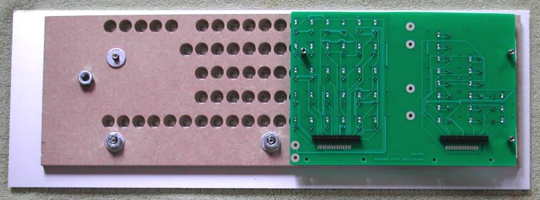
 Install the "Demux shift registers" board and the "Mux and carrier" board on the headers of the lights boards. First
check that the boards also rest on the stand-offs when they are mounted on the headers. Shorten the stand-offs or put
some washers on them to obtain the correct length.
Install the "Demux shift registers" board and the "Mux and carrier" board on the headers of the lights boards. First
check that the boards also rest on the stand-offs when they are mounted on the headers. Shorten the stand-offs or put
some washers on them to obtain the correct length.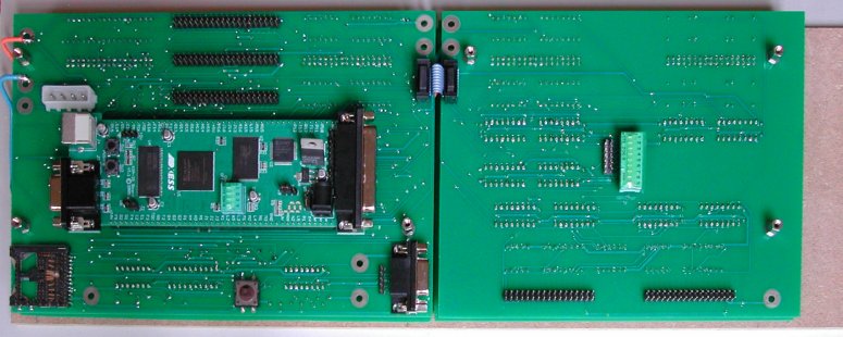
| back to top |
... lots more to do ...
| back to top |
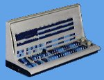
My idea was to build a housing as the PDP-15 console, that is the switch panel has a small slope horizontally, and the lights panel
has a steeper slope so that you look straight at the bulbs when the unit is placed on a table. A table-top 8i so to speak.
I had drawn the design of the housing in MS Visio (I know, sorry ... just using the tools available to me) and was working on drawing
the shapes of the side panels with Front Panel Express when a very interesting discussion started on the ClassicCmp maillist.
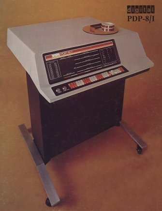
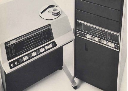
Somebody had found a design from |D|I|G|I|T|A|L| where the pdp8/i was built on a pedestal.
Pictures were found on the great Data General website of Bruce Ray
"I've even asked Rick Merrill (the creator of FOCAL) who was with DEC in the '60s if he had seen a pedestal system, and even he
had only heard that one existed for marketing but could not confirm this. It looked like a fun configuration to work with though."
Update September 2019
I mentioned the pedestal 8i on the PiDP-11/70 list (a great follow-up project of the PiDP/8i from Oscar Vermeulen).
First I got a reply from Charles Lasner (yes, the famous PDP8 guru), saying
I was going to mention the pedestal, but I also was not able to verify its existence beyond some either mockups
or CSS or Traditional Products offerings.
And then Chris Degen sent a reply ...
I remember a pedestal style PDP-8 that was at Brookhaven National Laboratory circa 1978. It was on display at
the Exhibit Center, located in old BGGR graphite reactor containment building. The reactor was decommissioned in 1968. The PDP-8 was
set up to play tic-tac-toe for visitors.
I’ve been unsuccessfully googling to find information about this machine for some time now. I expanded my search to other PDP models,
and even just minicomputers. I was beginning to doubt my memory. Clearly, the search term that was missing, was "pedestal".
My memory always said it was a PDP-8. I remember it being curvier, but that memory was likely corrupted over the intervening 40+ years.
I believe this is the machine I remember, so it looks like did exist.
So, it looks like the "pedestal 8i" actually did exist!
The idea of my construction is almost identical to the "pedestal 8/i version". On the "pedestal 8/i version", the panel lock switch and power switch are mounted horizontally next to each other, whereas these switches are mounted vertically above each other on the rack-mounted pdp8/i. As that was my only example at the time, my pedestal 8/i version has the switches also vertically aligned.
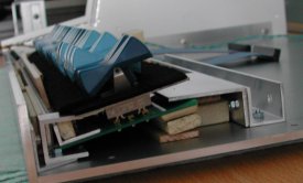
I forgot to add threaded holes on the rear side of the switches front panel to mount the switches-PCB to that panel, and I did
not want to drill holes that would be visible on the front panel. So, the switches-PCB is installed on the bottom cover of the
housing instead of onto the rear side of the switches front panel. To get the switches-PCB positioned at the correct angle and height
relative to the switches front panel, I used small wooden laths used to stir paint. They are glued together with double-sided tape.
Aluminum brackets keep the switches-PCB locked in place. Those were foreseen in the design phase, so no new holes had to be drilled :-)
I glued black felt cloth on a piece of carton and placed that around the switches. The small opening between the switches and the front
panel is now nicely dark (sort of "black hole"). The switches front panel is clamped in the grooves of the side panels. The little
tolerance put into the design to make sure that everything will fit together is minimized with glue and a small strip of carton at one
side of the front panel.
The following pictures give an impression how I mounted the switches-PCB. It is a bit of a "kludge", but effective ...
|
|
|
The two L-shaped profiles mounted to the U-shaped profile serve two purposes. They hold the switches-PCB in place, and are a support
for the lights front panel. Again, to obtain the correct height, I glued a few wooden laths onto the L-shaped profiles.
To protect the art work and the surface of the lights front panel, and have some sort of cover over the holes of the lamps, I ordered
samples of pieces of thin plastic that are "anti-reflective" and "frosted". I wanted to see how a thin plastic plate in front of the
lights front panel would look, whether the text writing would still be clean, etc. The frosted sample looked very nice as cover for
the holes of the lamps, but the text writing on the front panel became fuzzy. The "anti-reflective" piece was available in two
different plastics. One of them made the overall look of the front panel a bit gray-ish. The other piece looked nice enough though.
I installed the more reflective side against the aluminum front panel, so you look at the less reflective side.
I designed the width of the grooves in the side panels that will hold the lights front panel 1 mm larger, so that a thin plastic
cover could be neatly installed. Glad that I had thought of that! See the frontal and rear side pictures. The plastic protective
front cover rests almost perfect against the aluminum front panel, and I expect that it will be perfect when the horizontal rods
at both sides of the front panel are mounted. I still have to get those drawn and made ...!
The front panel with the plastic cover must be installed against the front edge of the groove in the side panels. L-shaped profiles
are mounted on the side panels at the top (to mount the top cover) and at a position near the bottom edge of the front panel. The
length of these L-shaped profiles is such that the ends will keep the front panel with the plastic cover against the front edge of
the groove in the side panels.
|
|
The power supply must be capable of a few Amps at +5 Volt and at least 4 Amps at +12 Volt. I bought a 150 W micro-ATX power supply
of Yuan-Kee, model YK-063, on eBay for just 10 euro. The nice thing about micro-ATX power supplies is that, besides the power OFF/ON
switch, they have a connection pin "Power-On" which must be connected to GND to start up the power supply. If this signal is not
connected to GND, the power supply is almost switched off, it is in a sort of stand-by status. All supply voltage outputs are off,
except the +5 Volt-Standby. The "Power-On" wire is connected to the Power On key switch of the front panel. With this solution the
AC power is safely inside the micro ATX power supply. According to the micro ATX specification the Power-On wire should be green,
but the color of that wire on the YK-063 is gray!
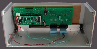
The power supply is installed at the rear side. I choose to position the power supply in the middle, because at the left hand side
(when viewed from the rear side) are the connections on the XESS module for the parallel port and the serial port, and at the right
hand side are the three 40-pin headers for expansion. With the power supply in the middle the cabling from the XESS module and
carrier PCB can be fairly straight to the rear panel.
At both sides of the power supply are L-shaped profiles that will be used to mount the rear panel. Those L-shaped profiles are
mounted against the sides of the power supply, and a U-shaped profile is installed against the rear side of the power supply, thus
keeping the power supply in place. A bracket at the rear side and the small screws at the front side of the power supply completes
the mounting of the power supply.
... lots more to do ...
| back to top |