- the few discrete resistors (not the SIL resistor arrays)
- the two ferrite beads
- the picofuse F1
- the zener diode D2 (1N5339)
The Front Panel PCB (Printed Circuit Board) is designed to have its own +5 Volt power supply, created from an external simple DC power supply like a "wall wart" that outputs 9 to 12 Volt. The external power supply connects via the picofuse F1, the on-board power ON / OFF switch, the protection diode D1 (1N5820, which protects against wrong polarity connection of the power supply) to the on-board voltage regulator REG1.
Personally, I do not like hot components mounted on a circuit board. If you want to install a 2�" IDE hard disk instead of a CF card, you may also need +12 Volt. In that case, a small PC power supply is a good choice. As the PC power supply outputs +5 Volt, you must remove the protection diode D1, because of its voltage drop, and solder a wire instead. This means that you loose the protection against wrong polarity connection, so better check twice before turning on the power! Further, you do not need the regulator and solder a wire jumper from pin #1 to pin #3. Make sure (for example by a short piece of insulation tube) that the wire jumper can not make contact with pin #2. While at it, now is a good moment to decide if you want to use the on-board ON / OFF switch S1. If you mount the FP6120 in an enclosure, this switch is probably never used, so solder a wire jumper for S1 instead.
To conclude this step, solder the sockets for all ICs. The sockets are not included in the kit from Spare Time Gizmos, and my
advice is that you buy good quality machined pin sockets. After all, the SBC6120 and FP6120 are not cheap, so why saving one dollar
on some cheap sockets of dubious quality?
As Bob suggests in the FP6120 manual, solder machined pin sockets for the LED resistor arrays, RP1,
RP1, RP3 and RP4. All 4 arrays are located above the LED bar. The
machined pin sockets will make a few experiments later on easy to determine the light output of the LEDs to your personal taste
and the environment where the Front Panel will be set.
You can solder the 4 SIL resistor arrays RP5, RP6, RP7, and
RP8 (value 4k7) directly on the PCB. Three are located below the switches, the fourth SIL array is left of the
rotary switch. Make sure that the common pin #1 (often indicated by a small dot on the SIL package) goes into the square pad on
the PCB. If you are not sure which pin is pin #1 of the SIL package, get the Ohm meter. Connect one lead to pin #1 and check on 3
other pins if the measured resistance is always approximately 4700. If you measure a value approximately 9400, you have not pin #1,
but the pin on the opposite side!
Finally, solder all decoupling capacitors next to the IC sockets, the tantalum and electrolytic capacitor.
Make sure you get the polarity of the tantalum and electrolytic capacitor correct!
| back to "top" |
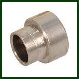 The swage standoffs were difficult things for me. I knew what standoffs are, but I had never heard of the term "swage".
So I looked it up in the dictionary, but buying these critters (here in The Netherlands) was not possible. I asked Vince, and he was so kind to buy some 30 "swage standoffs" and ship them to me. Vince got the swage standoffs from Jameco, the part number is 1582428. NOTE for non-US citizens: all mounting material is "inch stuff", not metric, so if you live in a European country, get the metal and nylon screws and spacers with threading from a US-based supplier. Shops here only sell the metric stuff.
Again, read the FP6120 manual very careful, as some of the "solder in swage standoffs" are placed on the component side of the PCB (and soldered on the solder side of the PCB), and some of them are placed on the solder side (and thus soldered on the component side of the PCB).
- 7 swage standoffs for the LED bar
- 5 swage standoffs for the SBC6120
- 5 swage standoffs for the IOB6120
- 4 swage standoffs for the 2�" hard disk
- 4 swage standoffs for the CompactFlash adapter
The plastic LED bar is mounted on the component side of the FP6120 Front Panel PCB with 7 metal #4-40 countersunk screws. See figure 4 in the FP6120 manual. The 7 swage standoffs for the LED bar are placed on the component side of the PCB, thus soldered on the solder side of the PCB.
You need a soldering iron that has sufficient heat capacity, I used a soldering iron of 75 Watt to solder the swage standoffs. A soldering iron used to solder electronic components like resistors etc. has not sufficient heat capacity. Make sure that the rim of the swage standoffs rests on the component side of the PCB, that is, that the screws will mount in an angle of 90 degrees to the PCB. I used a piece of painter's tape to keep the swage standoffs in the holes of the PCB and, after turning the PCB over to the solder side, the swage standoffs rest on a flat piece of wood. Do not let the swage standoffs rest on your desk. To solder them you must apply quite some heat, and you do not want burn marks on your desk!
Blow gently over the just soldered swage standoff and let the soldered swage standoff cool down before you proceed to the next one to prevent to much heat in the PCB.
The SBC6120 is mounted on the rear (solder) side of the FP6120 Front Panel PCB with 5 nylon #4-40 spacers. See figure 5 in the
FP6120 manual. The 5 swage standoffs for the SBC6120 are placed on the solder side of the PCB, thus soldered on the
component side of the PCB.
Read the tips given in "7 swage standoffs for the LED bar". First solder the 3 swage standoffs that are "in line" at the left
side (seen from the solder side), near the rotary switch, then solder the other 2 swage standoffs.
The IOB6120 is mounted on the rear (solder) side of the FP6120 Front Panel PCB with 5 nylon #4-40 spacers. See figure 5 in the
FP6120 manual. The 5 swage standoffs for the SBC6120 are placed on the solder side of the PCB, thus soldered on the
component side of the PCB.
Read the tips given in "7 swage standoffs for the LED bar". First solder the 3 swage standoffs that are "in line" at the right
side (seen from the solder side), at the short edge of the PCB, then solder the other 2 swage standoffs.
At this moment (February 2010), a new I/O board is being developed, so I do not have the board yet. I assume that the form
factor will be identical to the original IOB6120 board, at least as far as mounting concerns.
The 2�" IDE hard disk is mounted on the rear (solder) side of the FP6120 Front Panel PCB with 4 metal #4-40 spacers. See
figure 5 in the FP6120 manual. The 4 swage standoffs for the hard disk are placed on the solder side of the PCB, thus
soldered on the component side of the PCB.
Read the tips given in "7 swage standoffs for the LED bar". First solder the 2 swage standoffs that are "in line" at the left
side (seen from the solder side), at the short edge of the PCB, then solder the other 2 swage standoffs.
At this moment (February 2010), I have not yet mounted the hard disk, but I suspect that you can not mount the hard disk
directly onto the spacers. That may depend on the screw holes in the chassis of the hard disk. Perhaps some sort of bracket
must be installed on the spacers, and the bracket will hold the hard disk.
The CompactFlash adapter is mounted on the rear (solder) side of the FP6120 Front Panel PCB with 4 metal #4-40 spacers. See
figure 5 in the FP6120 manual. The 4 swage standoffs for the CF adapter are placed on the solder side of the PCB, thus
soldered on the component side of the PCB.
Read the tips given in "7 swage standoffs for the LED bar". First solder the 2 swage standoffs that are "in line" at the left
side (seen from the solder side), at the short edge of the PCB, then solder the other 2 swage standoffs.
I do not have a CF adapter and I suspect that there are CF adapters with mounting holes that do not fit on these spacers.
In that case some sort of bracket must be installed on the spacers, and the bracket will hold the CF adapter.
Even if you have not yet decided whether your mass-storage device for the SBC6120 will be a hard disk or a CompactFlash card, you can solder the 4 swage standoffs for the hard disk and the 4 swage standoffs for the CF adapter. As the device that you select in the end will be mounted on spacers, the not-used swage standoffs of the other device do not pose any problem. If you solder the 4 swage standoffs of the device you select now, and do not solder the other 4 swage standoffs, and you change your mind regarding the mass-storage device after you finished the assembly of the FP6120, it is nearly impossible to mount the other 4 swage standoffs. In that case you will have to kludge some bracket to be mounted on the "wrong" 4 swage standoffs. I did not solder the swage standoffs for the CF adapter. If I will ever want to use a CF card, I will put a piece of aluminum on the spacers for the hard disk and mount the CF adapter on that aluminum plate.
| back to "top" |
If you have used the SBC6120 before you bought the FP6120, the CPREQ connection already has a short 2-pin male connector on the SBC6120 with a jumper installed on it. That implies that you must mount a female header for J5 on the solder side of the FP6120 (and solder the 2 pins on the component side), or remove the 2-pin male connector on the SBC6120 and mount the 2-pin female header instead. The second option is risky, because you might damage the SBC6120 PCB. So, I removed the jumper (and kept the 2-pin male connector) and mounted a 2-pin female header on the FP6120 using the same procedure to get it at the correct height.
Get the polarity and the soldering height of the LEDs correct! Personally, I did not like the red LEDs that other builders used to complete the Front Panel. It just does not seem right, but that is my opinion, my taste. I also saw a few movies of front panels of running pdp8 systems on YouTube, and that strengthened me even more to buy "warm-white" LEDs instead. If the light is "too white", or you want to approach the warm white, yellowish light of an incandescent bulb you can always put a thin foil of (appropriately) colored plastic between the LED bar and the Front Panel. To experiment with the light output it is mandatory that you install machined pin sockets on the FP6120 PCB for the SIL resistor arrays, as I described earlier. That is important, because it is amazing how little current the white LEDs need. The movie clip (see step 7) shows the LEDs with series resistance of 2200 Ohm!
| back to "top" |
It is not mentioned in the FP6120 manual, but you must put a jumper on the pins of 30Hz ENABLE, otherwise you will not see much "blinkenlight" effects on the LEDs.
Finally, the last soldering action (for now...). Check that the "tang washer" of the rotary switch is in the correct position. If it is, the rotary switch has 4 positions. Read paragraph 2.5.6 of the FP6120 manual. Do the following steps to determine the length of the shaft. You need to have the knob you want to use for this switch.
- Put the knob completely on the shaft of the rotary switch. Use a pencil to mark the end of the knob (the side where the knob will be against the Front Panel). The length of the mark (let's call it "A") till the end of the shaft is the length that must protrude from the Front Panel.
- Remove the nut and the lock washer from the rotary switch.
- Put a marker line (with the pencil) on the shaft of the rotary switch at the surface of the Front Panel. Let's call this line "B".
- Add the length of marker "A" to the end of the shaft to the marker line "B". That is where you cut off the excess length of the shaft.
Before you solder the rotary switch, make sure that you cut the length of the shaft correctly. Put the pins of the rotary knob in the PCB and put the Front Panel on the PCB. Now, if you slide the knob over the shaft, the knob should rest or almost rest on the face of the Front Panel. If the distance between the rear end of the knob and the face of the Front Panel is too much to your liking you can file the shaft a little shorter. After you removed the Front Panel and took the rotary switch from the PCB! It is wise to keep a tiny distance between the knob and the Front Panel to prevent scratches on the Front Panel caused by the rim of the knob while you rotate it.
 Take the necessary precautions before handling static-sensitive devices like ICs.
The installation of the ICs is straight forward. Bend all pins on either side of the DIL IC package so that the IC fits nicely on the machined pin socket. Then push the IC gently into the socket.
Take notice of the correct orientation! All ICs have the same orientation, the notch or indent on the package must be at the side of the LED bar.
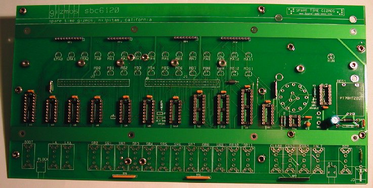
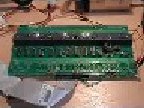
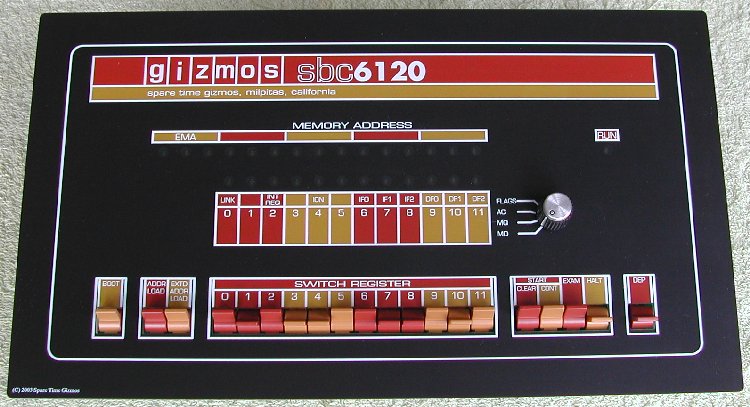
The image on the right shows the result with all electronic components soldered, and the SBC6120 mounted on the rear side. If you click on the image a .mpg movie starts (size is 3.5 Mb). It shows the LED activity after powering up, the entry of the "B" command to boot OS/8 and then the result after entering the ".DIR" command.
You can see moving a part of my hand to press the "Shift" key to enter the ".DIR" command in capitals.
| back to "top" |
BUT ... You must decide before you solder the switches whether you like the color of the switches. If you want to change the color of the levers of the switches after they are soldered on the PCB, you will have to remove the levers from the switches, with all the risk of damage to them!
Painting the levers of the switches
The problem here is to find paint that matches the color of the Front Panel as closely as possible. May be you can take the
Front Panel to a shop where they can measure the color and then produce the color, but it will probably be quite expensive.
I did find a shop capable of this job, but one color would cost some 70 to 80 euro (that is approximately US $100) and you need
two colors ... However, they could supply "standard" colors for just 18 euro per spray can. This paint is for example used on cars.
Painting the levers is not different of painting any other surface. If you follow these steps the result should look good.
- First of all, divide the switches in two groups of which the levers must have the same color.
The switches of the Switch Register (SR0 - SR11) and the HALT are "ON/OFF" switches (having two positions).
All other switches are momentary switches (having one position, if pushed to the other position and released, the switch returns to the initial position). 6 "ON/OFF" switches and 4 momentary switches must have the darker brownish color. - Degrease the levers.
- Use fine-grained sandpaper to make the surface of the levers a little "rough".
- Blow the dust from the levers, then degrease the levers again.
- Using the pins, mount all switches that must be painted in the same color on a piece of foam or cardboard.
- Spray a thin layer of primer on the levers. The primer will increase the bonding strength of the paint.
- After the primer has dried (10 to 15 minutes), spray a thin layer of the paint.
Do not try to cover the entire surface of the lever with paint in this first layer. - After the first layer of paint has completely dried, apply a second layer. Again, just a thin layer!
- Repeat step 8 for a third thin layer. If the color coverage is OK, you are done else an other thin layer is needed.
- Repeat steps 2 to 9 for the other lighter color, but that is obvious.
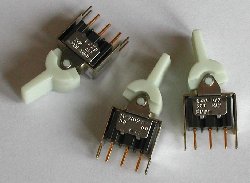
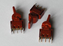
| before the primer is applied | after the dark paint is sprayed | after the light paint is sprayed |
|---|---|---|
 |
 |
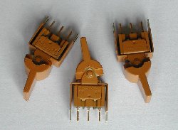 |
Due to the light, especially the color of the dark painted switches seems wrong, but here is the final result after soldering the switches
on the PCB. One tip: If you have not already soldered the rotary switch: don't! It is easier to solder the switches when the (long)
shaft of the rotary switch is not resting on the desk. If you painted the switches put a soft cloth on the desk. The cloth prevents the
first scratches on the top of the levers when the PCB is turned over to solder the pins. I soldered one switch at a time, and only the
center pin. For alignment I pushed every switch "upward" in the direction of the LED bar. It does not matter in wich direction you push
the switches as long as you are consequent. This will give the best alignment. Actually, I did not need to re-align a single switch. They
were all perfectly "in line".
The nut on the rotary switch makes the total height just too much, so that the hexagonal standoffs of the Front Panel are not resting on
the PCB. I removed the nut, but then a small space remains between the tang washer and the rear side of the Front Panel. I have cut a small
ring of felten that fits over the threading of the rotary switch. That keeps the tang washer in place and can never make "noise" against the
Front Panel.
| back to "top" |