| SYSTEM OVERVIEW | 11/70 |
This is my PDP-11/70 system. It is not the most expanded system that I have at home (that is my PDP-11/35).
The PDP-11/70 is the biggest UNIBUS based machine that D|I|G|I|T|A|L built.
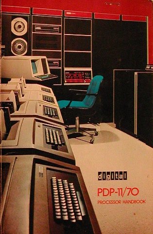
D|I|G|I|T|A|L introduced the PDP-11/70 in February 1975.
The PDP-11/70 is the high-end of the PDP-11
architecture that supports the speed, addressing range and bandwidth required in large systems applications. The PDP-11/70 was
the first PDP-11 that uses cache memory.
In a normal configuration, the PDP-11/70 processor is housed in one tall H960 industrial 19" cabinet. A second cabinet next to
the processor contains the system memory, either magnetic core, MOS memory or a combination of both. The memory is housed in an
expansion box, and one cabinet provides room for 4 expansion boxes. All peripheral devices were installed in additional cabinets.
Due to lack of space (a common problem among collectors), I installed the one memory expansion box above the processor in the
same cabinet. Sufficient room is between the processor and the memory box for the cooling. I do not run this system for long
times (say, several hours), so the temperature in the cabinet stays ok. As well as the energy bill, because this system is
quite power hungry!
At this moment I have only the following peripherals connected to the PDP/11-70 system.
The PDP-11/70 has two separate busses, one for the system memory and one for the peripheral I/O devices. The peripherals all
communicate via MASSBUS controllers with the central processor. The backplane of the 11/70 offers the
possibility to install 4 MASSBUS controllers. Each controller can connect several devices like tape and disk drives.
At the far end of the 11/70 backplane are a few UNIBUS slots available. These can be used to interface to the system console,
a printer, and all other Small Peripheral Controller devices like the interface for RX or RL drives, SDI drives, a network
interface, etc. However, the I/O bandwidth of these devices is limited by the UNIBUS. The MASSBUS
offers a better I/O performance.
Jumps within this page are:
The front panel of the PDP-11/70 has a few more buttons, switches and lights than the average Personal Computer, as you can see.
I guess this is what makes these old systems 'beautiful', compared with a modern PC. The full console of the PDP-11/70 is the most
elaborate one compared with all the "blinkenlight" consoles found on other PDP-11 processors.
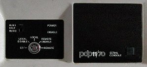
The PDP-11/70 is also available with a so-called remote console. This remote console is less "flashy" - it has only a system power
key switch, a remote push button and just a few indicator lights.
You install an M8255-01 (KY11-RE) Serial Console Control Module in slot 40 to which you can connect modems (or terminals ?) that
offer the same functionality as the full console.
The PDP-11/70 system does not need to be nearby to control it, so this is an ideal option for remote service of the machine. As I
have this version of the PDP-11/70 as well, I hope to figure out how to operate such a remote controlled 11/70 in the future.
Yup, I have two 11/70 systems in my collection!
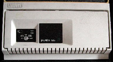
However, these two consoles are not the only consoles for the PDP-11/70 machine.
Here you see the console of the so-called "Industrial 11/70".
The "Industrial 11" was developed for use in processing and manufacturing applications.
Control over the system via the (full) console
| PDP-11/70 programmer's console indicators | ||
|---|---|---|
| 16 DATA lights | The data display lights are used to show the 16-bit word data just examined or deposited, or other data within the CPU. | |
| PARITY HIGH / LOW |
The PARITY HIGH and LOW lights indicate the parity bit for the respective bytes on read operations. On write operations these two lights are off. The interpretation of the data is determined by the Data Select switch. | |
| 22 ADDRESS lights | The ADDRESS lights are used to show the address of data being examined or just deposited. The address is interpreted as a Virtual or a Physical address as determined by the Address Select switch. | |
| S T A T U S |
PAR ERR | The PAR ERR lights to indicate a parity error during a reference to memory has occurred. |
| ADRS ERR | The ADRS ERR lights to indicate that one of the following addressing errors occurred.
| |
| RUN | The CPU is executing program instructions. If the instruction being executed is a WAIT instruction, the RUN light will be on. The CPU will proceed from the WAIT on the receipt of an external interrupt, or on console intervention. | |
| PAUSE | The CPU is inactive because the current instruction execution has been completed as far as possible without more data from the UNIBUS or memory, or the CPU is waiting to regain control of the UNIBUS. | |
| MASTER | The CPU is in control of the UNIBUS (UNIBUS Master only when it needs the UNIBUS). The CPU relinquishes control of the UNIBUS during DMA and NPR data transfers. | |
| USER SUPER KERNEL |
The CPU is executing instructions in USER , SUPERvisor or KERNEL mode. | |
| DATA | When the DATA light is on, the last memory reference was to D address space in the current CPU mode. If the light is off, the last memory reference was to I address space in the current CPU mode. | |
| ADDRESSING 16 18 22 |
'16' - on when the CPU uses 16-bit mappings. '18' - on when the CPU uses 18-bit mappings. '22' - on when the CPU uses 22-bit mappings. | |
| PDP-11/70 programmer's console switches and buttons | |
|---|---|
| 22 ADDRESS/DATA switches |
The 22 ADDRESS/DATA switches set a 16- to 22-bit address to be loaded or the 16-bit data to be stored in a
processor register or a memory location as determined by the control switches and the Address Select switch. These switches are called the Switch Register, and the switches 15-0 can also be read from a program that is running. |
| This white button is not labelled. It is the Lamp Test button. It is used for maintenance purposes. When the Lamp Test button is raised, all console indicator lights are turned on. An indicator that does not light is defective and must be replaced. | |
| LOAD ADRS | Depressing the LOAD ADRS button down, causes the contents of the Switch Register to be loaded into the Address Display. The address displayed is a function of the position of the Address Select switch. |
| EXAM | The EXAM button causes the contents of the current location specified in the Address Display to be displayed in the Data Display register when the Data Select switch is in the DATA PATHS position. The address in the Address Display will be mapped or unmapped depending on the position of the Address Select switch. The location displayed in the Address Display lights is also a function of that switch. |
| DEP | The physical operation of the DEPOSIT button
requires it to be lifted for actuation. The DEP button causes the current contents of the Switch Register to be
deposited into the address specified by the current contents of the Address Display. The address in the Address Display will be mapped or unmapped depending on the position of the Address Select switch. The location displayed in the Address Display is also a function of that switch. |
| CONT | Depressing the CONT button causes the CPU to resume execution. The CONT button has no effect when the CPU is in the RUN state. |
| ENABLE/HALT | The ENABLE/HALT switch is a 2-position switch used to stop machine execution and to enable the system to run. |
| S/INST S/BUS CYCLE |
The S/INST - S/BUS CYCLE switch only affects the operation of the CONTinue button. It controls if the machine stops after an instruction or a bus cycle. This button has no effect on any switches when the ENABLE/HALT switch is in the ENABLE position. |
| START | The function of the START button depends on the setting of the HALT/ENABLE switch. ENABLE - Start execution HALT - Clears the computer system (init). |
Control over the system via the remote console
Thanks to Edward, I have the information from the little booklet "Electronic Console Commands", EK-E1170-MC-001.
The push button in the right lower corner is a "LAMP TEST".
The console has 3 separate states: Program I/O, Console, and Talk.
| Key switch position description / Slide switch position description | |
|---|---|
| OFF | Turns CPU and electronic console off. |
| LOCAL DISABLE | ^P recognition disabled, disables all console functions. |
| LOCAL | ^P recognition enabled, enables all console functions at local terminal. |
| REMOTE DISABLE | ^P recognition disabled, disables all console functions, forces local copy. |
| REMOTE | ^P recognition enabled, enables all console functions at remote terminal. |
| RUN 1 | Initialize Switch Register to all zeroes. |
| HALT | Disable Power Fail restart. |
| RUN 0 | Initialize Switch Register to all ones. |
| Indicator description | |
|---|---|
| POWER | Indicates that the console has power. |
| DISABLE | ^P recognition disabled (panel lock position). |
| REMOTE | Indicates that the Key Switch is in REMOTE. |
| TEST | Indicates that DDC host is testing. |
| FAULT | Indicates that the Electronic Console has a problem. |
| CARRIER | Indicates that someone remotely is communicating with the console. |
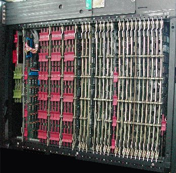
As usual, slot #1 is at the front side when you stand in front of the computer.
So, from front to rear you see the following main sections on the PDP-11/70 backplane.
| Back to top |