 The µPDP-11/93 was the last built PDP-11 model by DIGITAL. The introduction in May, 1990, of the PDP-11/93
and PDP-11/94 was at the 20th anniversary of the first PDP-11.
The µPDP-11/93 was the last built PDP-11 model by DIGITAL. The introduction in May, 1990, of the PDP-11/93
and PDP-11/94 was at the 20th anniversary of the first PDP-11.| SYSTEM OVERVIEW | µPDP-11/93 |
The µPDP-11/93 was the last built PDP-11 model by DIGITAL. The introduction in May, 1990, of the PDP-11/93
and PDP-11/94 was at the 20th anniversary of the first PDP-11.
Mentec.inc bought the hardware and software license from DIGITAL and continues to build PDP-11's, in the beginning based on the J11 chip (M70, M80, M90 models), but later they build PDP-11 compatible boards based on their own implementation of the processor.
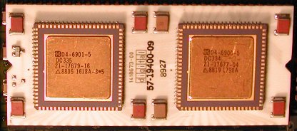
The µPDP-11/93 is the fastest PDP-11 from DIGITAL, and comes in two versions:
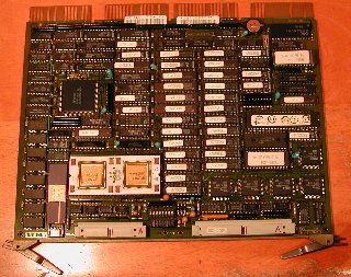 I do not have much information about the M8981 module, but the information I received was sufficient to get the system
running.
I do not have much information about the M8981 module, but the information I received was sufficient to get the system
running.
Thanks again, Douglas.
Between the two header connectors (left side: 40 pins, right side 60 pins) are 8 diagnostic LEDs.
Next to the 40-pin header is a yellow LED which indicates the +5 Volt power. Next to the yellow LED are 3 diagnostic red
LEDs, a green "DCOK" monitor LED and the again 3 diagnostic red LEDs. With the appropriate console/SLU panel at the rear,
these 8 LEDs are visible on two 7-segment displays.
Documentation
KDJ11-E CPU System Maintenance Manual, EK-403AA-MM-001.
Sorry, but I do not have that manual...
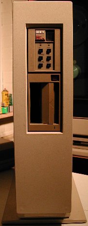
 This 11/93 is housed in a BA23 box.
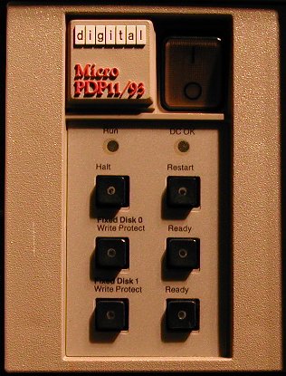
On the front you see the TK50 tape cartridge drive and the console.
Behind the front cover, below the TK50 sits the RD54 disk drive.
The system boots RSTS/E version 10.
console/SLU panel (rear side)
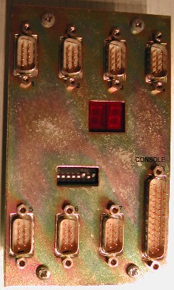 On the rear panel are the following parts:
| switch # | description |
|---|---|
| 1 | enable/diable console/SLU. To enable the console, the switch must be OFF. |
| 2-3-4 | select boot device 1 through 6. These are assigned via EEPROM parameters which can be set up in Dialog Mode. Interpret OFF=1, ON=0 and switch #2 is high-order bit and switch #4 is low-order bit. When these 3 switches are all set to OFF you get the normal auto boot mode. |
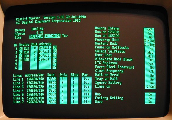
| 5 | Switch #5 set to ON enables "forced Dialog" after the ROM tests are complete. In Dialog Mode you have interaction via the console through a menu. See below. |
| 6-7-8 | Baudrate for the console port. The console port is hard-wired for 8 data bits, no parity and one stopbit. Switches set to ON-OFF-ON gives 9600 Bd. |
| Back to top |