VT30H COLOUR MIMIC DISPLAY SYSTEM
D|I|G|I|T|A|L CSS - Computer Special Systems |
VT30H / VTV30H / VT30HS |
INTRODUCTION
The VT30H Colour Display System is designed for use with PDP-11 computers. The VT30H drives a standard colour TV monitor
conforming to either CCIR 625 line TV standard or NTSC 525 line standard. The VT30H consists of just two modules, one hex-size
and one quad-size board. Three versions are available.
- VT30H - Colour Display System with UNIBUS interface
- VTV30H - Colour Display System with QBUS interface
VTV30HR - VTV30H, LSI-II microprocessor, memory and serial line interface in a self-contained 5.25" high box
- VT30HS - Colour Display System with serial interface
The VT30HS incorporates a microprocessor and enables the display controller to be connected to any D|I|G|T|A|L
computer via a single, full duplex serial line. The interface is designed to be as far as possible, software compatible with normal
serial connected input/output terminals. The VT30HS has the following features.
- error checking on each character
- input either EIA V24 or 20 mA current loop, hardware selectable
- when used in conjunction with the standard keyboard - full remote picture editing features
- full duplex operation at speeds up to 9600 Bd (hardware selectable 600, 1200, 2400, 4800, or 9600 Bd)
- retains all the important operational features of the standard VT30H
Further, the VT30HS can also be supplied in a free-standing self-contained box for remote operation. This option is called VT30HT.
Summary
- Alpha-numerics and graphics
- 8 colors
- Foreground / background color selectable
- Hardware flash
- Automatic cursor control
- Up to 128 user-defined characters
- Interface for UNIBUS, QBUS, and serial line
- Program selectable character size
- 525/625 line operation
AVAILABLE DOCUMENTATION
- VT30H: Colour Mimic Display System (OPTION BULLETIN SECTION 8 (E) JAN 78)
INSTALLATION
The VT30H consists of one hex-size module (M7114, video module) and one quad-size module (M8295, UNIBUS
control module). The board set fits in two adjacent SPC (Small Peripheral Controller) slots in a PDP-11 backplane. For the
VT30HS an additional standard serial line interface is needed.
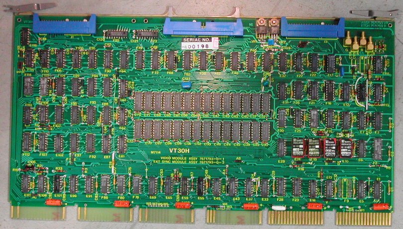
M7114 Video module
Connection to the monitor is realized using four 75 Ohm coaxial cables of 50 cm length. At the top of the M7114 are 4 SMA
(or is it SMB?) connectors. From top (edge of the board) they are labeled "B", "R", "S", "G", which probably stands for respectively
blue, red, sync, and green. I do not know what the purpose is of the header J3 next to the coaxial connectors. The other headers
(J1 and J2) connect to the M8295 module.
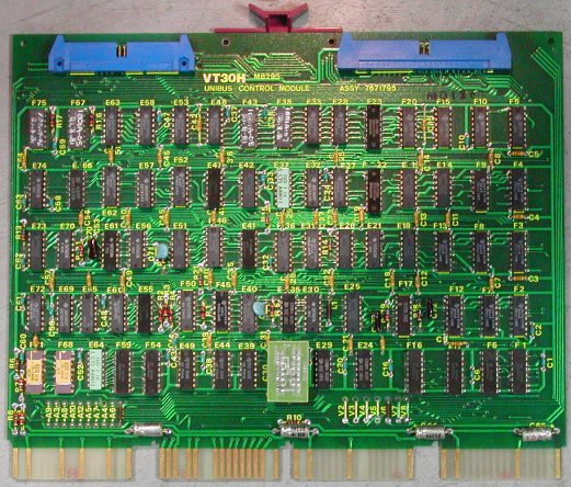
M8295 UNIBUS Control module |
The M8295 is installed in the slot next to the M7114, position C-F. The M7114 and M8295 are connected
using two "over the top" ribbon cables.
The bottom connection (J1 on M7114) is a 40-pin header and the interconnection cable is marked
MFG. CSS. RE. P/N 2K-EC-24A-AD.
The connection in the middle (J2 on M7114) is a 50-pin header and the interconnection cable is marked
MFG. CSS. RE. P/N 2K-EC-25A-AD.
- VT30H electrical requirements.
- +5V at 6 A
- +15V at 750 mA
- -15V at 3 mA
|
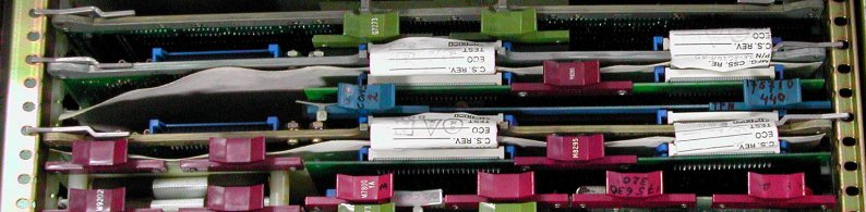
Two VT30H units installed in a PDP-11/94 system
SOFTWARE
Two software packages are available for use with the VT30H.
- Picture Editor Software
This software enables a user to simply and efficiently
- build or edit a picture
- build or edit a character set
- read back and save a picture and character set
- load a picture and character set
- create a Macro as a portion of a picture
- compress and expand pictures to minimise the storage space necessary.
The software runs on its own, and requires only a basic PDP-11 processor with a minimum of 8K words of memory, a VT30H and some
form of operator input device such as Teletype, DECwriter, VT30H Keyboard.
- RSX11M Software for VT30H
For users using D|I|G|T|A|L 's RSX11M Real Time Operating system, a comprehensive VT30H software package is
available which consists of 4 parts.
- The Device Handler - A conventional RSX11M multi-device handler capable of supporting all the VT30H features and can drive
up to 16 VT30H's independently.
- The Picture Editor - Provides all the facilities of the stand alone. Picture editor software outlined above plus some
additional features, run as a task under RSX11M.
- Subroutine library - Allows the user to operate on the VT30H from FORTRAN IV or MACRO programs.
- Macro library - Allows the user easy access to the various subroutines.
The VT30H programmer's model has 4 registers.
- CSR - Control and Status register
Used to control the operation of the device.
- DBUF - Data Buffer
Used to read and write picture information from/into the picture memory.
- CAR - Cursor Address Register
Contains the X-Y coordinates of the picture element being addressed. If enabled, the cursor will also appear at those coordinates.
The cursor position is indicated by the character at the X-Y coordinates being switches alternate negative and positive video
(cursor blink is jumper-selectable to one of four rates).
- CSR - Character Store Register
This register contains the address of the character currently being read from or written to the character memory, together with
the associated characters data.
All registers are read/write, and automatic register increment feature are included where necessary, to minimise the programming
effort required when loading a new picture or character set. The access time of the VT30H is such that "interrupt"-based operation
is not normally necessary.
The function of the video output section of the controller is to continually access the two memories, convert the information
retrieved to a video signal and output this to the TV monitor, in order to refresh the picture. Hence, having once loaded a picture
to the controller, no further action is then required from the host computer to maintain the display.