|
RK05 removable hard disk drive |
| RK11 controller |
Direct jumps to:
If you want to print this page on A4 or Letter format, set the scaling in the printer driver to 80%.
INTRODUCTION
 The RK05 is actually a family of disk drives.
The RK05 and the RK05J are removable hard disk drives, the RK05F is a fixed hard disk drive.
DIGITAL writes in the documentation that these drives are 'compact and lightweight'. Well, that depends on what you compare an RK05 to.
An RK05 or RK05J weighs 50 kg. and its dimensions are 19" (48 cm) wide, 10.5" (27 cm) high and 26.5" (67 cm) deep!
Compare this with a modern 3.5" floppy drive ... both drives accept a removable disk cartridge. The RK05/RK05J cartridge stores 2.5 Mbytes;
two 3.5" floppies store more than this.
AVAILABLE DOCUMENTION
- RK05/RK05J/RK05F disk drive maintenance manual (EK-RJ5JF-MM-001)
- RK05 disk drive maintenance manual (DEC-00-RK05-DA)
- RK05J Engineering Drawings
- RK05 disk drive engineering drawings
- RK11-C moving head disk drive controller manual (DEC-11-HRKA-D)
- RK11-C moving head disk drive controller engineering drawings
(DEC-11-HRKA-D)
- RK11-D and RK11-E moving head disk drive controller user's manual
(EK-RK11D-OP-001)
- RK11-D disk drive controller engineering drawings
- FCO (Field Change Order) FCO RK05-00064
- ECO RK05-00061, Air Handling
- ECO RK05-00055, Capacitor Bracket
- ECO G180-00008, Head Select
- ECO G180-00009, Data Reliability
- ECO 5409484-00005, Overvoltage
GENERAL DRIVE INFORMATION
| Drive specifications RK05/RK05J |
|---|
| Voltage | 115/230 VAC @ 50/60 Hz |
|---|
| Power | 250 W. |
|---|
| Starting current | power only | 1.8 A. |
|---|
start spindle | 10 A. for 2 sec |
| Data transfer rate | 1.44 Mbits/sec |
|---|
| Disk rotation | 1500 rpm |
|---|
| Average latency | 20 msec (half revolution) |
|---|
| Head positioning |
adjacent tracks | 0 msec |
|---|
average | 50 msec |
200 tracks movement | 85 msec |
|
|
The RK05 disk drive has a few variations. First, there is the RK05 and the RK05J drive. I do not know what the differences are.
There is also an RK05/f, and this drive is almost identical to the RK05 disk drive ... The RK05/f is a "fixed-disk" drive,
as the "/f" suggests. The removable pack is the same for both drives, but the RK05 cartridge is installed permanently in an RK05/f drive.
The opening door with smoke-brown transparent plastic is replaced by a metal plate and the solenoid that locks the door when the drive is
in operation (or without power) is removed. The cartridge is held in place by springs that are attached to the cartridge and the drive.
As the cartridge is never removed from the drive the alignment is not lost, and this allows doubling the track density, and hence doubling
the storage capacity. The heads in the RK05/f drive are different to facilitate this doubled track density. You can recognize these heads
by the colour of the connectors at the end of the wires as these are blue, instead of white.
|
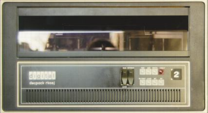
Controls and indicators
The drive has two controls.
| RUN/LOAD |
When this switch is placed in the RUN position the following actions will occur if all interlocks are save.
- the front door is locked
- the disk is accelerated to operating speed
- the read/write heads are loaded
- the RDY indicator is lit
|
|---|
| WT PROT |
When is spring-loaded switch is momentary placed in the WT PROT position, the
WT PROT indicator is lit and write operations to the disk are not possible.
Pushing this button will also turn the FAULT indicator off if it is lit.
Pressing WT PROT a 2nd time turns the WT PROT indicator off and allows write
operations to the disk. |
|---|
The drive has eight indicators.
| PWR |
The POWER indicator is lit when operating power is present. |
|---|
| RDY |
The READY indicator is lit when the following conditions are met:
- the disk is rotating at the correct operating speed,
- the heads are loaded,
- no other conditions are present (all interlocks safe) to prevent a seek, read or write operation.
The READY indicator turns off when the RUN/LOAD switch is set to LOAD. |
|---|
| ON CYL |
The ON CYLINDER is lit when the following conditions are met:
- the drive is in the READY condition,
- a seek or restore operation is not being performed,
- the read/write heads are positioned and settled.
The ON CYLINDER indicator turns off during a seek or restore operation. |
|---|
| FAULT |
The FAULT indicator is lit when
1. erase or write current is present without a WRITE GATE, or
2. the linear positioner transducer lamp is inoperative.
The FAULT indicator turns off when the WT PROT switch is pressed or when the drive goes through a RUN/LOAD sequence. |
|---|
| WT PROT |
The WT PROT indicator is lit when
1. the WT PROT switch is pressed, or
2. the operating system sends a Write Protect command.
The WT PROT indicator turns off when the WT PROT switch is pressed a second time or when the drive goes through a RUN/LOAD
sequence. |
|---|
| LOAD |
The LOAD indicator is lit when the read/write heads are fully retracted and the spindle stopped rotating. |
|---|
| WT |
The WT indicator is lit when a write operation occurs. It turns off when the write operation terminates. |
|---|
| RD |
The RD indicator is lit when a read operation occurs. It turns off when the read operation terminates. |
|---|
RK05 DISK CARTRIDGE
The disk is hard-sectored and can be either 12 or 16 sectors per track. The diameter is 14 inches, and the cartridge contains a
single platter. The "12-sector" cartridge is used in the PDP-11 environment, and the "16-sector" cartridge (which is less common!)
is used in the PDP-8 environment.
The same cartridge can be used in the RK05 and the RK05/f disk drive.
If you remove the cartridge from an RK05/f drive and put it back in the drive you should do a (low-level) format.
|
|
| Disk data storage information |
|---|
| | RK05/RK05J | RK05F |
|---|
| Density | 2200 bpi max. |
|---|
| Tracks/surface | 406 (200 + 3 spare) | 812 (400 + 6 spare) |
|---|
| Cylinders | 203 (2 tracks each) | 406 (2 tracks each) |
|---|
| sectors | 4872 (12 per revolution) | 9744 (12 per revolution) |
|---|
6496 (12 per revolution) | 12996 (16 per revolution) |
| Unformatted capacity | 25 million bits | 50 million bits |
|---|
|
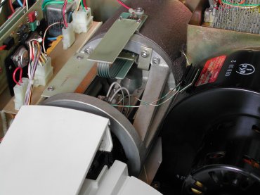
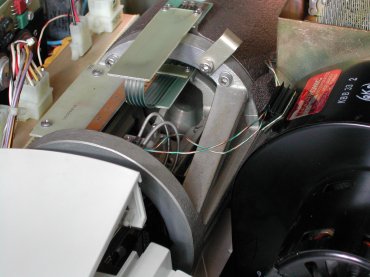
HOW TO TRANSPORT THE RK05 DRIVE
To securely transport a RK05 disk drive you must lock the read/write heads. This is a fairly simple procedure.
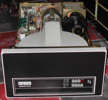
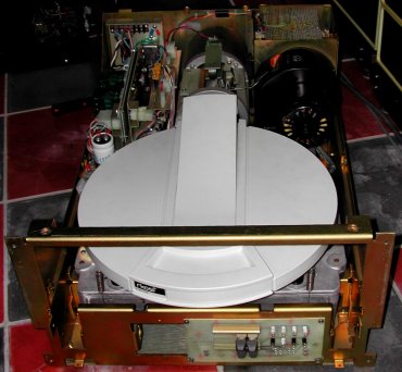
To lock the heads you must remove the top cover lid. The top cover lid is fixed to the drive with a few screws
at both sides of the drive. Unlock these screws and you can lift the top cover from the drive.
On the outer ring of the heads / moving coil assembly you can see a bracket that is fixed to this ring with
one screw. Loosen the screw a few turns and put the bracket in such a way that it does not block the movement
of the heads when they move out.
Note. Do not move the heads outward manually! When the heads are moved outward (without
a spinning disk) the heads will "slam" against each other, and damage can occur to the ceramic heads.
| RK05f top cover |
| RK05f top cover and front removed |
|---|
| |
|
| RK05 head carriage locked |
| RK05 head carriage unlocked |
|---|
| |
|
RK05 DRIVE ALIGNMENT
The RK05 disk drive needs proper alignment, in contrast to for example the RL01/RL02 disk drives. The RL01/RL02 disk drives
use a cartridge that has servo tracks written on the platter, and a head reads this data and the positioner adjust the
head carriage to keep the heads aligned on track.
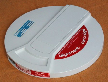
The RK05 cartridge does not have these servo tracks, instead the drive relies on a correct aligment which must be done
when ever the drive has been disassembled, for example when the heads are replaced.
You need a special cartridge to do the alignment procedure.
Make sure that the drive is set "WRITE PROTECTED" before you slide this special (rare, expensive) cartridge in the drive.
Also, make sure that the heads are clean! You do not want a head crash, and certainly not when the alignment cartridge
is in the drive!
If you only have one RK05 disk drive, and do not care about being able to read other packs than the ones written
on your drive, you do not need any alignment. A drive with misaligned heads will read its own packs. You can see
the alignment as a sort of "interchange-ability alignment".
There are 2 screws for each head. One screw clamps the head tail into the positioner carriage. The other screw pushes
the head forward when you turn it in. The aligment steps are the following.
- Loosen the first screw a few turns.
- Turn the other screw out.
- Push the head into the positioner as far as possible.
- Load the alignment pack.
- Slowly turn the second screw in, until the head is aligned.
- Tighten the first screw to fix the position of the head.
- Turn the second screw a few turns out to prevent this screw producing misalignment due to thermal effects.
So, from this procedure you can see that because of the last "official" step the chance to get a removed head in its
correct position is pretty slim without the alignment pack. You might get away with turning the second screw in
against the head before you loosen the first screw.
Then do step 1, replace the head, push it against the second screw and finally the last two steps.
It is just a suggestion ...
One other thing good to know is that the two heads are not the same!
There is a difference between "up" and "down" head and it has to do with the way the heads "fly" above the disk surface. The heads
need the correct amount of pressure toward the disk surface so that the flying height is correct. If the flying height is not correct,
you get low amplitude signals from the head (flying too high) or possibly head crashes (flying too low). For a head that flies above
the disk, gravitation and the head mounting springs push in the same direction. For a head that flies below the disk, gravitation pulls
the head away from the surface while the mounting springs push it to the surface.
CLEANING THE RK05 DRIVE AND THE HEADS
If the drive has not been used for a long time, do the following steps to keep the drive in good shape.
- Replace the NiCd battery pack (4 x AA) for the emergency head retract operation.
You do not want your fingers in the area of the heads in the head/voice coil assembly!
If you have ever seen the force with which the heads are retracted in a power-loss condition, you can imagine how
serious the injury can get.
- If a cartridge is in the drive (RK05/f), remove it.
- Inspect the heads for brown or black stains. If the heads need cleaning use isopropol alcohol with lint free wipes,
or at a stretch, cotton buds, but check after the cleaning that you did not leave any fibres.
- Check that the foam rubber around the duct that blows air into the disk cartridge is not desintegrated. No small
particles should come off when you slide a finger over it. If that is the case, replace the foam! I used foam which is
also used to make a door in a house free of drought.
- Check that the plastic parts are intact. With age this can get brittle.
- Power up the drive without the disk cartridge so that you can check that there is a decent air flow from
the absolute air filter and blow out the dust that would otherwise contaminate the disk cartridge. Set the Head Load
Disable switch so that the heads will not load, and run the drive for at least 30 minutes purge any dust.
I have also read another procedure to clean the heads.
- Power down the drive and disconnect the emergency retract batteries.
- Take a piece of reasonable quality paper like photocopy or inkjet paper.
Tear off a couple strips approximately 5" x 2.5", and fold it in 3, length-wise.
- Moisten the first paper with alcohol.
- Pull the head mechanism out and ensure that the heads clamp around the paper.
Do not let the heads "bang" against each other.
- Slide the paper back and forth and move down to a cleaner piece of the paper.
- Repeat the previous step until there are no dark marks on the paper anymore.
- Now take the second piece of paper (without alcohol) and slide it back and forth between the heads in the same way
for a few strokes. The dry paper is more abrasive. Move down the paper and do it again until there are no dark stains
on the paper. The heads are now be polished.
- Move the heads back in the home position! Then, connect the battery.
RK05 DRIVE MAINTENANCE
The prevous paragraph explains the importance of clean heads, and how to keep them clean.
The RK05 disk drives have other components that need to be looked after for problemless operation. First and most important
is the absolute air filter. Over time, this filter gets filled with small dust particles and that will cause a drop of the
air flow. If the air flow is low you can use a vacuum cleaner to suck air through the filter in the opposite direction.
Of course, the replacement with a new absolute air filter is the best option ...
Do the following steps to check the air flow.
- Power up the drive.
- Open the front foor.
- Carefully and gentle put a hand over the air plenum at the left side in the drive.
Be very careful with the plastic air duct between the absolute air filter and the plenum chamber when you remove / install
the absolute air filter. The plastic becomes brittle over time!
An other attention point in the RK05 disk drive are the NiCd batteries. These batteries supply the power for the emergency
head retract if the power to the drive fails. If you have a power failure, and these NiCd batteries are dead, the heads will
crash on the platter of the cartridge! So, check once a year if these batteries are still OK.
Do the following steps to check the NiCd batteries.
- Make sure no AC power is supplied to the drive.
- Pull the RK05 drive out of the rack until the screws at the rear side top cover can be loosened.
- Loosen the screws of the top cover (top front & rear side, and left & and right side).
- Remove the top cover.
- Measure the voltage of the NiCd battery pack. Notice the polarity !
- more to be added ...
RK11-D UNIBUS & QBUS INTERFACE
The RK11-D controller is a dedicated 4-slot system unit (backplane) and connects the following modules.
- slot 1 - M7254 - status control module
- slot 2 - M7255 - disk control module
- slot 3 - M7256 - registers module (data path)
- slot 4 - M7257 - bus control module
The four modules are all inserted in position C thu F of the slots. Slot 1, position A-B is the UNIBUS-IN
connection, and slot 4, position A-B is the UNIBUS-OUT connection.
Slot 2, position A-B is the connection to the first RK05 drive.
Slot 3, position A is either for the power harnass connection, or it is not used as the power hardnass is connected directly
(with AMP connectors) to the wiring side of the backplane.
Slot 3, position B is never used.
The RK11-D controller supports up to eight RK05 *logical* drives. There is a distiction between logical drive and physical drive.
The physical drive RK05 or RK05J counts as one logical drive, but the physical drive RK05/f counts as two logical drives,
of which the first logical drive has an even number assigned.
The connection from the RK11-D system unit to the first RK05 drive is the BC11A-xx cable.
This cable is also used to connect the other RK05 drives in the chain.
The BC11A-xx cable is available in several lengths which is indicated by the -xx suffix. The "xx" is the length of the cable measured
in feet. This cable is also used to connect UNIBUS system units in separate cabinets, and thus got the incorrect name "UNIBUS cable".
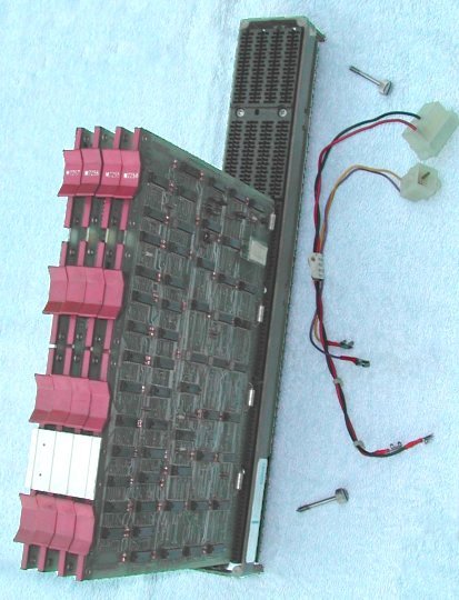
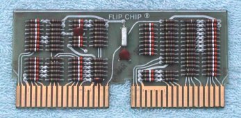
There is also an RK11-C controller. This controller is a lot larger, it has 4 rows of flip-chip cards, a separate power supply and
takes up 10.5" of rack space. The nice thing of this RK11-C controller is that it has a front panel with lots of "blinken"lights.
Looking at the rear side of the RK05 drive, the card cage is at the left side in the drive.
The two left-most slots are for connecting the BC11A cable DRIVE-IN and DRIVE-OUT. It does not
matter which slot you use for DRIVE-IN and DRIVE-OUT.
The last (or only) drive in the chain needs a terminator, and again, it does not matter in which slot you install the terminator
(DRIVE-IN or DRIVE-OUT).
The terminator module is the M930. It has resistors (discrete components or in DIL packages) to terminate the signal lines.
The first module, next to the two DRIVE-IN and DRIVE-OUT slots is the M7700. This module has a
small rotary switch that defines the physical drive number. For the RD11-D controller, the M7700 must be Rev. J or later.
There is also a RK11-D to QBUS adapter, called the RKV11, to connect RK05 disk drives in a QBUS-based system.
It is also a 4-slot back plane with 4 quad-height modules, of which 3 are the same as the modules in the RK11-D.
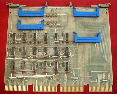
The fourth module, M7268, connects the 4-slot system unit to the QBUS. Here is a picture of that module.
I do not have this module, this picture is taken from an eBay auction. As far as I know the four blue BERG connectors connect to
a special cable. The other end of that cable is a dual-height card that goes into a QBUS slot.
RK11 CONTROLLER INSTALLATION
Before you install the RK11 subsystem in the PDP-11, check the 2 modules that have configuration jumpers. M7257 (Bus Control) has
7 jumpers for the interrupt vector address and 8 jumpers for the subsystem start address. The interrupt vector is typically 220 (octal),
and the start address is 777400 (octal). Further, there are 7 jumpers on the M7257 that (when cut) inhibit the loading of a
particular programmable register.
On the module M7254 (Control Status) is the interrupt level jumper, which is typically BR5.
On the module M7255 (Disk Control) is a switch that sets the clock source. It should be set to AUTO for the
RK11 internal crystal clock.
More details to be added ...
- Check that the wiring of the RK11 backplane is not damaged.
- Install the System Unit (backplane) in the PDP-11 with the 2 screws.
- Install the UNIBUS-IN connection
- a BC11A-xx cable from the previous (expansion) box
- an M9202 module from the previous system unit in the same box
- Install the 4 RK11 modules in their correct position.
- Install the BC11A-xx disk drive cable in slot 2, position A-B.
- Install the UNIBUS-OUT connection
- a BC11A-xx cable to the next expansion box
- an M9202 to the next system unit in the same box
- the M9302 terminator module.
- Connect the power wiring for the RK11 system unit. This is either 2 cables directly attached to the wiring side of the
backplane, or a small FlipChip that is inserted into slot 3, position A, and has cables that must be guided to the power
connections.
RK11 CONTROLLER REGISTERS
The RK11 has 7 registers assigned to memory locations in the address space of the PDP-11. The default start address for the RD11
controller is 777400. The other registers are at consecutive word addresses, but note the gap between register 6 and 7!
| address | mnemonic | register description |
|---|
| 777400 | RKDS | RK11 Drive Status register (read only) |
| 777402 | RKER | RK11 Error register (read only) |
| 777404 | RKCS | RK11 Control Status register |
| 777406 | RKWC | RK11 Word Count register |
| 777410 | RKBA | RK11 Bus Address register (current memory address) |
| 777412 | RKDA | RK11 Disk Address register |
| 777414 | | not used |
| 777416 | RKDB | RK11 Data Buffer register |
- RKDS - RK11 Drive Status register (read only)
| bit | Designation | Description and Operation |
|---|
| 00 - 03 |
Sector Counter (SC) |
These 4 bits are the current sector address of the selected drive. Sector address 00 is defined as the
sector following the sector that contains the index pulse. |
| 04 |
Sector Counter equals
Sector Address (SC=SA) |
Indicates that the disk heads are positioned over the disk address currently held in the sector address.
|
| 05 |
Write Protect Status (WPS) |
Set when the selected disk is in the write-protect mode. |
| 06 |
Read/Write/Seek Ready (R/W/S RDY) |
Indicates that the selected drive head mechanism is not in motion, and that the drive is readu to accept
a new function. |
| 07 |
Drive Ready (DRY) |
Indicates that the selected disk drive complies with the following conditions :
- The drive is properly supplied with power.
- The drive is loaded with a disk cartridge.
- The disk drive door is closed.
- The LOAD/RUN switch is set to RUN.
- The disk is rotating at the correct speed.
- The heads are properly loaded.
- The disk is not in a DRU (bit 10 of the RKDS register) condition.
|
| 08 |
Sector Counter OK (SOK) |
Indicates that the Sector Counter operating on the selected drive is not in the process of changing,
and is ready for examination. If this bit is not set, the Sector Counter is not ready for examination, and a second
attempt should be made. |
| 09 |
Seek Incomplete (SIN) |
Indicates that due to some unusual condition a Seek function connot be completed. Can be accompanied by
bit 15 of the RKER register (Drive Error).
Cleared by a Drive Reset function. |
| 10 |
Drive Unsafe (DRU) |
Indicates that an unusual condition has occurred in the disk drive, and it is unableto properly perform
any operations. Reset by the LOAD/RUN switch to LOAD. If, when the switch is returned to RUN, the condition recurs, an
inoperative drive can be assumed, and corrective maintenance procedures should be begun.
Can be accompanied by bit 15 of
the RKER register (Drive Error). |
| 11 |
RK05 Disk on Line (RK05) |
Always set, to identify the selected disk drive as RK05. |
| 12 |
Drive Power Low (DPL) |
Set when an attempt is made to initiate a new function, or if a function is actively in the process
when the control senses a loss of power to one of the disk drives. Can be accompanied by bit 15 of the RKER register
(Drive Error).
Reset by a BUS INIT or a Control Reset function. |
| 13 - 15 |
Identification of Drive (ID) |
If an interrupt occurs, these bits will contain the binary representation of the logical drive number
that caused the interrupt. |
- RKER - RK11 Error register (read only)
| bit | Designation | Description and Operation |
|---|
| 00 |
Write Check Error (WCE) |
Indicates that an error was encountered during a Write Check function as a result of a faulty bit
comparison between disk data and memory data. Clears upon the initiation of a new function. This is a soft error condition.
|
| 01 |
Checksum Error (CSE) |
Sets while performing a Read Check or a Raed function as a result of a faulty recalculation of the checksum.
Cleared upon the initiation of any new function.
This is a soft error condition. |
| 02 - 04 |
|
Unused. |
| The remaining bits of the RKER register are all hard errors, and are cleared
only by a BUS INIT or a Control Reset function. |
| 05 |
Nonexistent Sector (NXS) |
Indicates that an attempt was made to initiate a transfer to a sector larger than 13 (octal). |
| 06 |
Nonexistent Cylinder (NXC) |
Indicates that an attempt was made to initiate a transfer to a cylinder larger than 312 (octal). |
| 07 |
Nonexistent Disk (NXD) |
Indicates that an attempt was made to initiate a function on a nonexistent drive. |
| 08 |
Timing Error (TE) |
Indicates that a loss of timing pulses for at least 5 �s has been detected. |
| 09 |
Data Late (DLT) |
Sets if during a Write or Write Check function when the multibuffer file is empty and the operation is
not yet complete. Sets during a Read function when the multibuffer file is filled and the operation is not yet complete.
|
| 10 |
Nonexistent Memory (NXM) |
Sets if memory does not respond with a SSYN within 20 �s of the time when the RK11 becomes bus master
during an NPR sequence. Because of the speed of the RK05 Disk Drive, it is possible that NXM will be accompanied by bit 09
(Data Late). |
| 11 |
Programming Error (PGE) |
Indicates that RKCS 10 (Format) was set while initiating a function other than Read or Write. |
| 12 |
Seek Error (SKE) |
Sets if the disk head mechanism is not properly positioned while executing a normal Read, Write, Read
Check, or Wite Check function. The control checks 16 times before flagging this error. A simple jumper change will force
the control to check just once. |
| 13 |
Write Lockout Violation (WLO) |
Sets if an attempt is made to write on a disk that is currently write-protected. |
| 14 |
Overrun (OVR) |
Indicates that, during a Read, Write, Read Check, or Wite Check function, operations on sector 13 (octal),
surface 1 of cylinder address 312 (octal) were finished, and the RKWC has not yet overflowed. This is essentially an
attempt to overflow out of a disk drive. |
| 15 |
Drive Error (DRE) |
Sets if one of the drives in the system senses a loss of either AC or DC power and a function is either
initiated or in process while the selected drive is not ready or in some error condition. |
- RKCS - RK11 Control Status register
| bit | Designation | Description and Operation |
|---|
| 00 |
GO (write only) |
Loaded by the operator. Causes the control to carry out the function contained in bits 01 through 03 (Function)
of the RKCS register. Remains set until the control actually begins to respond to GO, which may take from 1 �s to 3.3 ms,
depending on the current operation of the selected drive (to protect the format structure of the sector).
|
| 01 - 03 |
Function (read/write) |
The Function register, or function bits, are loaded with the binary representation of the function to be
performed by the control when a GO command is initiated. These bits are loaded by the program and cleared by BUS INIT. They
retain the function until altered by the program or cleared, enabling the user to continue from a soft error condition with GO.
| Bit 2 | Bit 1 | Bit 0 | Operation |
|---|
| 0 | 0 | 0 | Control Reset |
| 0 | 0 | 1 | Write |
| 0 | 1 | 0 | Read |
| 0 | 1 | 1 | Write Check |
| 1 | 0 | 0 | Seek |
| 1 | 0 | 1 | Read Check |
| 1 | 1 | 0 | Drive Reset |
| 1 | 1 | 1 | Write Lock |
|
| 04 - 05 |
Memory Extension (MEX - read/write) |
Reserved for extended bus addresses used in conjunction with the RKBA register. This 2-bit counter
increments each time the RKBA overflows. A bus DATO to these bits overrides any RKBA overflow. Loaded by the program and
cleared by BUS INIT. Use of these bits is intended for systems equipped with a memory larger than 32K words.
|
| 06 |
Interrupt on Done Enable
(IDE - read/write) |
When set causes the control to issue a bus request and interrupt to vector address 220 if :
- A function has completed activity.
- A hard error is encountered.
- A soft error is encountered and bit 08 (SSE) of
the RKCD register is set.
- RKCS register bit 07 (RDY) is set and GO is not set.
|
| 07 |
Control Ready (RDY - write only) |
Indicates that the control is ready to perform a function. Set by INIT, a hard error condition, or by
the termination of a function. Cleared by GO being set.
|
| 08 |
Stop on Soft Error (SSE - read/write) |
If a soft error is encountered when this bit is set, then
- all control action will stop at the end of the current sector if RKCS register bit 06 (IDE) is reset, or
- all control action will stop and a bus request will occur at the end of the current sector if RKCS register bit 06 (IDE) is set.
|
| 09 |
Extra Bit (EXB) |
For the RK11-D and RK11-E, EXB is unused.
|
| 10 |
Format (FMT - read/write) |
FMT is under program control, and must be used only in conjunction with normal Read and Write functions. Used
to format a new disk pack or to reformat any sector erased due to control or drive failure. Alters the normal Write operation,
under which the header is rewritten each time the associated sector is rewritten, in that the head positioner is not checked
for proper positioning before Write. Alters the normal Raed operation in that only one word, the header word, is transferred
to memory per sector. For example, a 3-word Read function in Format mode will transfer header words from 3 consecutive sectors
to 3 consecutive memory locations for software checking.
|
| 11 |
Inhibit Incrementing the RKBA
(IBA - read/write) |
Inhibits the RKBA register from incrementing during a normal transfer function. This allows data transfers
to occur to or from the same memory location throughout the entire transfer operation.
|
| 12 |
|
Unused.
|
| 13 |
Search Complete (SCP - read only) |
Indicates that the previous interrupt was the result of some Seek or Drive Reset function. Cleared at the
initiation of any new function.
|
| 14 |
Hard Error (HE - read only) |
Sets when any of the RKER register bits 05-15 are set. Stops all control action, and processor reaction is
dictated by bit 06 (IDE) of the RKCS register, until cleared, along with bits 05-15 of the RKER register, by INIT or a
Control Reset function.
|
| 15 |
Error (ERR - read only) |
Sets when any of bit of the RKER register sets. Processor reaction is dictated by bit 06 (IDE) and bit 08 (SSE)
of the RKCS register. Cleared if all bits in the RKER register are cleared.
|
- RKWC - RK11 Word Count register
The bits in this register contain the 2's complement of the total number of words to be affected or transferred by a given function.
The register increments by one after each word transfer. When the register overflows (all WC bits go to zero), the transfer is
complete and the RK11 operation is terminated at the end of the present disk sector. However, only the number of words specified
in the RKWC register are transferred.
- RKBA - RK11 Bus Address register
The bits in this register contain the bus address to or from which data will be transferred. The register is incremented by two
at the end of each transfer. If the system has extended memory, the RKBA register will overflow to the EX MEM (bits 04 and 05 of the
RKCS register) to reflect the extended bus addresses.
- RKDA - RK11 Disk Address register
This register will not respond to commands while the controller is busy. Therefore, RKDA bits are loaded from the bus
data lines only in the Control Ready (RDY - bit 07 of the RKCD register) state, and are cleared by BUS INIT and Control Reset. The
RKDA register is incremented automatically at the end of each disk sector.
| bit | Designation | Description and Operation |
|---|
| 00 - 03 |
Sector Address (SA) |
Binary representation of the disk sector to be addressed for the next function. |
| 04 |
Surface (SUR) |
When active, enables the lower disk head so that operation is performed on the lower surface.
When inactive, enables the upper disk head. |
| 05 - 12 |
Cylinder Address (CYL ADDDR) |
Binary representation of the cylinder address currently being selected.
The largest valid address or number for the cylinder address is 312 (octal). |
| 13 - 15 |
Drive Select (DR SEL) |
Binary representation of the logical drive number currently being selected. |
- RKDB - RK11 Data Buffer register (read only)
The bits of this register work as a general data handler in that all information transferred between the control and the disk drive
must pass through this register. Loaded from the bus only while the RK11 is bus master during an NPR sequence.
CONTROLLER DIAGNOSTICS
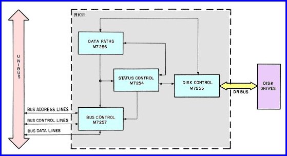
The diagram shows the relation between the 4 modules and their interfaces. This is helpfull if you have problems with the RK11/RK05
subsystem.If everything seems fine as seen from the PDP-11, but something is wrong at the drive's side, your first inspection
would go to the M7255 module.
If the PDP-11 has problems (bus hang or crash), you would check the module M7257.
If the subsystem seems to work fine but you read the wrong data, check for a stuck databit on the module M7256.
The RK11/RK05 subsystem has the following diagnostics:
| | «-»
| ZRKH(x) | RK11 / RK05F/J performance exerciser |
| | «-»
| ZRKI(x) | RK11 / RK05F/J utility package |
| | «-»
| ZRKJ(x) |
RK11 / RK05F/J basic logic test #1 |
| | «-»
| ZRKK(x) | RK11 / RK05F/J basic logic test #2 |
| | «-»
| ZRKL(x) |
RK11 / RK05F/J dynamic test |
The (x) represents the revision level.
RK05 BOOTSTRAP DATA
Loading or toggling in this data enables the PDP-11 to boot from the RK05 disk. As this is a very short bootstrap,
you can impress all your friends by remembering the 9 instructions. Imagine their faces when you turn on the big PDP-11
system, flip the switches of the switch register, load a cartridge in the RK05 drive and say "Now we wait until
the drive has spun up". Then you load the start address and press the START switch.
The physical appearance of the RK05 disk drive (the lights that flicker, and the view inside the drive) is very
appealing, and almost leaves the same strong impression you get when you look at an open-reel tape drive in motion!
This bootstrap is taken from the RT-11 V5.5 installation manual.
How to load a bootstrap program and start the execution.
|
| | x0 | x2 |
x4 | x6 |
|---|
| 001000 | 012700 | 177406 | 012710 | 177400 |
|---|
| 001010 | 012740 | 000005 | 105710 | 100376 |
|---|
| 001020 | 005007 | | | |
|---|
* The start address is 001000.
|