 The RX01 has two 8" drives capable of single density only.
Inside the drive are two boards: a controller (M7726) and a read/write board (M7727).
Through an interface board this RX01 was connected to the computer system.
| RX01 / RX02 8" floppy disk drive |
| RX11 / RX211 controller |
Floppy disks on these old machines are 8 inches in size and exist in single and double density.
High density was not yet invented.
The RX01 has two 8" drives capable of single density only.
Inside the drive are two boards: a controller (M7726) and a read/write board (M7727).
Through an interface board this RX01 was connected to the computer system.
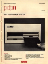
full size RX01 option bulletin (785x1038 pixels, 284 kb)
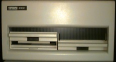
 The RX02 has also two 8" drives, but can read and write double density floppies. The two boards inside this drive are
the controller (M7744) and the read/write board (M7745). The controller board inside the RX02 has two DIP switches
and thus the drive could be configured to work as an RX02 for a PDP-11 (or LSI-11) with data transfer using DMA, as
an RX01 for all three systems using programmed I/O data transfer, or as RX02 for the PDP-8 only with data transfer on
programmed I/O basis.
The RX02 has also two 8" drives, but can read and write double density floppies. The two boards inside this drive are
the controller (M7744) and the read/write board (M7745). The controller board inside the RX02 has two DIP switches
and thus the drive could be configured to work as an RX02 for a PDP-11 (or LSI-11) with data transfer using DMA, as
an RX01 for all three systems using programmed I/O data transfer, or as RX02 for the PDP-8 only with data transfer on
programmed I/O basis.
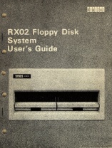
full size RX02 User Guide (785x1038 pixels, 625 kb)
|
The interface logic for the RX01 is the following.
|

|
The interface logic for the RX02 is the following.
|
| Back to top |
![]()
| Back to top |
| Drive specifications RX01/RX02 | |
|---|---|
| Height | 26.67 cm (10.5") |
| Width | 19" rack size compatible |
| Depth | 43.18 cm (17") |
| Weight | xx kg (60 lb) |
| Power | 200 W max (dual drive) |
| Data storage capacity | ||
|---|---|---|
| RX01 | RX02 | |
| Number of surfaces | 1 | |
| Number of tracks/surface | 77 | |
| Number of sectors/track | 26 | |
| Number of 8-bit bytes/sector | 128 | 256 |
| Formatted capacity (bytes) | 256256 | 512512 |
|
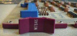
The diskdrive interfaces to the UNIBUS with the ° M7846 (RX01 controller) or the ° M8256 (RX211 controller) via a 40-wire flat ribbon cable with a length of 15 foot (4.57 meters). The DEC partnumber is BC05L-15. The RX02 disk drive can be modified to read and write RX01 formatted floppies. In the drive on the internal controller board (M7744) is a 2-way DIP switch. | ||||||||||||||||||||||||
| Back to top |
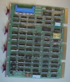
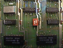 The upper board inside the RX02 drive is the M7744 controller.
| full view of the M7744 board (122 kb) |
| subsystem | system | S1-1 | S1-2 | * |
|---|---|---|---|---|
| RX211 RXV21 | PDP-11 LSI-11 | OFF | ON | note 1 |
| RX8E RX11 RXV11 | PDP-8 PDP-11 LSI-11 | ON | OFF | note 2 |
| RX28 | PDP-8 only | OFF | OFF | note 2 |
| Back to top |
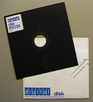 The media used on the RX02 floppy disk system is compatible with the IBM 3740 family of equipment. The diskette
is encased in a plastic envelope with a large slit for the read/write head, a centre hole for the drive spindle
hub and a hole for track index sensing. The diskette is soft-sectored, and the media is preformatted in
an industry-standard compatible format.
The media used on the RX02 floppy disk system is compatible with the IBM 3740 family of equipment. The diskette
is encased in a plastic envelope with a large slit for the read/write head, a centre hole for the drive spindle
hub and a hole for track index sensing. The diskette is soft-sectored, and the media is preformatted in
an industry-standard compatible format.
If you have a system with an RX02 installed, you can "reformat" RX01 disks. The formatting process, however,
is not actually a real "format writing". It accepts a pre-formatted disk with the 128-byte single density data
sectors (and the single density headers), and rewrites the data sectors as 256-byte block sectors.
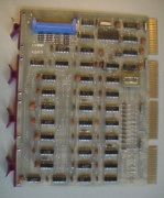 The RX11 UNIBUS controller for the RX01 drive has the number M7846 on the handle.
Here should come an explanation, XXXXXXX, the chips on the board, etc.
Note that the RX01 is a polled-I/O device, so the NPR wire must be intact!
The RX211 UNIBUS controller is for the RX02 drive and has M8256 on the handle.
 The RX211 controller board for UNIBUS has the code M8256.
The default CSR, (Command & Status Register -
the base address), is 177170 (octal of course) and this is set by the 10-way DIP switch. SW1 is on the
left and is for A3, SW10 is for A12.
When the switch is in the "off" position it represents a
binairy '1'.
So the standard RX211 address is 1111001111 on this DIP switch. The 10-way DIP switch
is in the picture at the bottom on the opposite side of the BERG connector which accepts the flatcable
going to the drive.
The 7-way DIP switch is for setting the interrupt vector. For the RX211 it defaults to 264.
When the switch is in the "off" position it represents a binairy '0'.
SW1 is vector bit 2, SW7 is
vector bit 8. So the standard RX211 vector is 1011010 on this DIP switch. This 7-way DIP switch is located
between the backplane connectors C and D.
The priority level is standard set to BR5 and can be changed by inserting another plug in the socket located near backplane connector D and below the 7-way DIP switch.
As the RX02 is normally configured as a DMA device you must cut the NPR jumper on the backplane for the slot
where the M8256 is seated. The NPR jumper wire is on pins CA1 - CB1.
The M8256 controller represents 2 bus loads on the UNIBUS, and needs 1.8 A. maximum at 5 Vdc.
| Back to top |
The RX11 (M7846) subsystem has two diagnostics:
| «-» | ZRXA(x) | system reliability test |
| «-» | ZRXB(x) | interface diagnostic |
| «-» | ZRXD(x) | RX02 performance exerciser |
| «-» | ZRXE(x) | RX02 formatter program |
| «-» | ZRXF(x) | RX02 function/logic |
| ZRXC(x) | RX02 utility driver (Brutus) |
| Back to top |
Loading or toggling in this data enables the PDP to boot from the floppy disk.
This bootstrap is taken from the RX01/RX02 Pocket Service Guide, EK-RX012-PS-002.
As I have not (yet) connected the RX11 controller with the RX01, I can not check this code at the moment.
It requires a system generation if you want to have two floppy disk controllers in a single system.
I want to add the RX11 to the RX211 which is already in the PDP-11/35. If I only had time ....
How to load a bootstrap program and start the execution.
The start address is 001000.
| x0 | x2 | x4 | x6 | |
|---|---|---|---|---|
| 001000 | 005000 | 012701 | 177170 | 105711 |
| 001010 | 001776 | 012711 | 000003 | 005711 |
| 001020 | 001776 | 100405 | 105711 | 100004 |
| 001030 | 116120 | 000002 | 000770 | 000000 |
| 001040 | 005000 | 000110 |
Loading or toggling in this data enables the PDP to boot from the floppy disk.
This bootstrap is taken from the RX01/RX02 Pocket Service Guide, EK-RX012-PS-002.
I have entered this code and my PDP-11/34A and my PDP-11/35 just boot fine.
How to load a bootstrap program and start the execution.
The start address is 002000.
| x0 | x2 | x4 | x6 | x0 | x2 | x4 | x6 | |
|---|---|---|---|---|---|---|---|---|
| 002000 | 012701 | 177170 | 012700 | 100240 | 005002 | 012705 | 000200 | 012704 |
| 002020 | 000401 | 012703 | 177172 | 030011 | 001776 | 100440 | 012711 | 000407 |
| 002040 | 030011 | 001776 | 100433 | 110413 | 000304 | 030011 | 001776 | 110413 |
| 002060 | 000304 | 030011 | 001776 | 100422 | 012711 | 000403 | 030011 | 001776 |
| 002100 | 100415 | 010513 | 030011 | 001776 | 100411 | 010213 | 060502 | 060502 |
| 002120 | 122424 | 120427 | 000007 | 003737 | 005000 | 005007 | 000000 |