INTRODUCTION
AVAILABLE DOCUMENTION

- TE16 Field Maintenance Print Set
(MP00333)
- TE16/TE10W/TE10N DECmagtape Technical Manual (EK-0TE16-TM-001)
- TE16/TE10W/TE10N DECmagtape transport user's manual (EK-TEWN-OP-001)
- TE16 DECmagtape Pocket Service Guide
(EK-0TE16-PS-001)
- TM03 Magnetic Tape Formatter Technical Manual (EK-0TM03-TM-002)
GENERAL DRIVE INFORMATION
RH11 MASSBUS UNIBUS INTERFACE
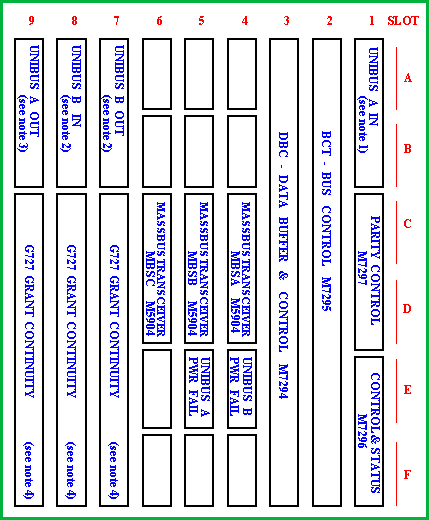
The RH11 controller consists of a dedicated 9-slot backplane in which the RH11 modules are seated.

Notes (see RH11 backplane image).
- 1. UNIBUS A IN.
- may be either M920 (connection from adjacent device) or BC11A cable (connection from other box or non-adjacent
device).
- 2. UNIBUS B IN and OUT.
- may be M9300 (termination at beginning or end of UNIBUS B) or BC11A cable (connection to other BUS B devices).
- 3. UNIBUS A OUT.
- may be either M920 (connection from adjacent device), M930 (termination at end of UNIBUS A) or BC11A cable
(connection to next box or non-adjacent device).
- 4. G727 Bus Grant Continuity (slot 7-8-9).
- The Grant modules must be inserted at position D in all three slots. Basically, the slots 7-8-9, positions C thu F
are Small Peripheral Controller (SPC) slots. However I have a bulletin that says that the SPC slots may not contain
any controllers because of the power drain via the backplane. Since they are SPC slots they require a G727 in position D.
The empty slot positions are not used, the UNIBUS Power Fail modules are M688 boards.
CONTROLLER DIAGNOSTICS
The RH11/TE16 subsystem has the following diagnostics:
The (x) represents the revision level.
TE16 BOOTSTRAP DATA
Loading or toggling in this data enables the PDP to boot from the TE16 tape.
How to load a bootstrap program and start the execution.
The start address is 001000.
table comes here.

