INDEPENDENT SIDEBAND ADAPTOR
|
RA.121A/B INDEPENDENT SIDEBAND ADAPTOR |
|
| HIGHLIGHTS |
|
|
|
|
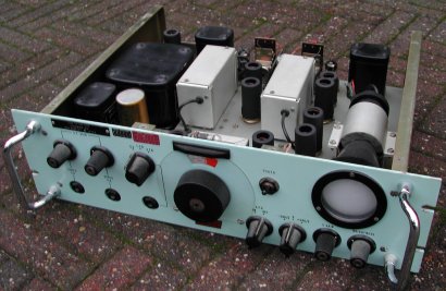
The RA.121A and RA.121B adaptors are self-contained having a built-in power unit, and are designed to operate from the 100 kc/s i.f. output of the receiver. The only differences between the A and B models are in the mains connection and adjustment arrangements and the input socket.
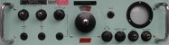
The "A" model is for the British market and has the following visual recognizable items.
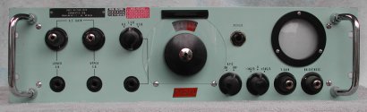
The "B" model is for the North American market. Here is a description of this unit.
The "D" model has a crystal controlled oscillator instead of an LC oscillator for increased stability.
The i.f. input signal of 100 kc/s to the RA.121, fed via a preset potentiometer, is mixed with the output of a stable 118 kc/s oscillator. This oscillator is variable over a range of +/- 2 kHz and is fitted with a slow motion drive which provides an accurate control of tuning essential to take full advantage of the carrier and unwanted sideband rejection characteristics of the unit, and to avoide pitch disdortion. A further control in the form of a three position switch alters the frequency by +/- 3 kc/s.
 The mixer output, centred at 18 kc/s, is fed via a 12 to 24 kc/s (18 kc/s +/- 6 kc/s) band-apss filter, carrier
rejection bridge stage and an amplifier stage to both upper and lower sideband filters. The filters provide a
high degree of rejection to all signals other than the wanted sideband.
The mixer output, centred at 18 kc/s, is fed via a 12 to 24 kc/s (18 kc/s +/- 6 kc/s) band-apss filter, carrier
rejection bridge stage and an amplifier stage to both upper and lower sideband filters. The filters provide a
high degree of rejection to all signals other than the wanted sideband.
Each sideband filter output is mixed in a product detector, with a signal at 18 kc/s, from a fixed frequency
oscillator, giving products including an audio component. Unwanted signal frequencies are subsequently removed
by means of further filter network. The resultant output therefore consists only of the audio frequencies.
The audio frequency on each channel is fed to an a.f. output stage with a gain control and having three
independent outputs, one of which is provided with a switch for sideband selection.
A Cathode Ray Tube (C.R.T.) functions as a tuning indicator. The 18 kc/s carrier re-insertion oscillator output is applied to the X plates and the input carrier signal taken from the band-pass filter is applied to the Y plates through a two-stage tuned amplifier. This gives a Lissajous presentation showing a stationary ellipse when the input carrier frequency, after the first mixer, is the same as the frequency of the carrier re-insertion oscillator, (18 kc/s), that is when tuning of the input signal is correct.
A simple form of a.f.c. is provided for optional use to maintain correct tuning over a small range of drift of either the input signal or the internal oscillators. H.T. and heater supplies are included in the equipment, making it entirely self-contained.
The adaptor is designed for rack mounting or for fitting in a suitable cabinet above the RA.17 receiver.
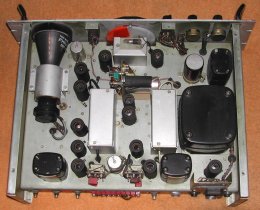
All electrical connections with the exception of the headphones are made at the rear side of the unit.
A dust cover is fitted which provides adequate ventilation and at the same time ensures ample protection from
dust and dirt.
Tubes
| Functional use | Type number RA.121A | mil. code | Type number RA.121B |
|---|---|---|---|
| Mixer | 6AS6 | CV2522 | 6AS6 |
| 118 kc/s oscillator | 6AU6 | CV2524 | 6AU6 |
| 18 kc/s amplifier | EFC82 | CV5065 | 6U8 |
| 18 kc/s rejector | 12AX7 | CV492 | 12AX7 |
| Sideband amplifier | 12AT7 | CV455 | 12AT7 |
| 18 kc/s oscillator | 12AT7 | CV455 | 12AT7 |
| U.S.B. detector | 6AS6 | CV2522 | 6AS6 |
| L.S.B. detector | 6AS6 | CV2522 | 6AS6 |
| H.T. rectifier | 6X4 | CV493 | 6X4 |
| U.S.B. output | EF91 | CV138 | EF91 |
| L.S.B. output | EF91 | CV138 | EF91 |
| C.R.T. indicator | DG7-32 | CV2431 | DG7-32 |