| General UNIBUS information | UNIBUS |

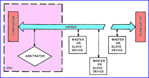
The UNIBUS consists of groups of wires that carries specific electrical signals to which all modules in
PDP-11 UNIBUS-based computer are connected. The UNIBUS is a transmission medium that
interconnects the so-called bus devices of the system. As the transmission lines in the UNIBUS have a
characteristic impedance, both ends must be properly terminated. This is accomplished by a UNIBUS
terminator module, or on the processor module itself.
The wires in the UNIBUS can be classified in 3 groups.
The following names are introduced to understand the operation of the UNIBUS.
| Back to top |
The function of the UNIBUS is to allow data to be exchanged between devices as directed by the program. The
program is a sequence of instructions as interpreted by the processor. Data is transmitted on the bus either as 16-bit words or as
8-bit bytes. The data exchange is always between a master and a slave. The master determines which device will become slave by
putting the address of the desired slave device on the bus. In order to become bus master a device must request and obtain the use
of the data section. This request may be made any time the device is ready for a data transfer. Any number of devices may be
asserting a request at the same time. The priority scheme implemented by the arbitrator determines which of these requests is
honored, that is, which device will obtain the use of the data section when it becomes free. Several devices may be ready to
transfer data at the same time. Since only one of these devices can obtain the use of the data section, the other requesting devices
have to wait before being allowed to transfer data. If the wait time is too long, some devices may lose data. This wait period is
known as latency.

Signals on the UNIBUS can be divided into 2 general categories.
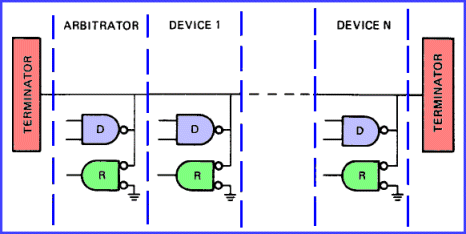
The majority of the bus signals use lines that are wired-OR circuits to which the inputs to the bus receivers (green) and the outputs to the bus drivers (purple) are connected. These lines are available along the length of the UNIBUS to any device.
Five UNIBUS signals use lines where the signal is received only by the device that is closest on the line to
the origin of the signal. This receiving device, in turn, either re-transmits the signal to the next device on the line, or does
not re-transmit the signal ("blocks" the signal). The transmission process continues until either a device blocks the signal or
the end if the line is reached. These lines are used only by the arbitrator to grant bus access permission to devices requesting
the use of the data section of the bus.

A priority structure determines which requesting device will use the data section of the bus. The priority is a function of (1) the priority level assigned to the device, and (2) its position on the bus with respect to other devices of the same priority level. All devices, with one exception, may be assigned to one (or more) of 5 hardware priority levels. Each of these levels has a dedicated signal line. Each signal line is driven by all bus devices assigned to the priority level. These 5 lines are called Bus Request lines (NPR, BR7, BR6, BR5, BR4) and are monitored by the arbitrator. A device that requires the use of the data section asserts a request on one of these lines. The arbitrator issues a grant to the highest priority request active. A grant signal informs the requesting device that it may become next bus master. This grant signal is sent on a separate line, NPG, BG7, BG6, BG5, BG4. The level of the grant is the same as that of the request. The arbitrator issues a grant to the first device on the bus assigned to the same priority level as the grant. If this device is requesting the use of the data section, it accepts and acknowledges receipt of the grant. It also blocks further transmission on the grant line. If the device is not requesting the use of the data section, it passes the grant to the next device on the same grant line. This procedure is repeated until a device accepts the grant or until the end of the bus is reached. In the latter case, the grant is cancelled by the arbitrator and the arbitration process is restarted. All devices assigned to a given priority level have higher priority than any device at a lower level. Within a given priority level, the device closest to the arbitrator (origin of grant signal) has the highest effective priority.
An address is the name of a location in memory of a register. A number specifies the location. A UNIBUS device
may contain one or more locations. A simple device such as a line clock may contain only one; a memory device may contain thousands.
A device may be able to store many words and yet have only 3 or 4 address locations. An example of this is a disk controller. An
address location may be used for storage of data or for control of a device.
A PDP-11 16-bit word is divided into a low byte (bits
0-7) and a high byte (bits 8-15). A 16-bit word used for addressing can address a maximum of 32K words (or 64K bytes). However, the
top 4096 word locations are reserved for peripheral register addresses, and the user therefore has 28K words for programs. Systems
with Memory Management options provide an 18-bit effective memory address which permit addressing up to 124K words of memory for
programs.
A device must be bus master to use the address lines. An address put on the address lines by a master is received by
all bus devices that are capable of becoming slaves. One of these devices recognizes its address and becomes the slave. The slave
does not know which device is master nor where the master is physically located on the bus. The master does not know the physical
location of its slave, nor does it need to know. Each external I/O device has an external page address assigned to it. The use of
this address on the UNIBUS is defined as part of the PDP-11 I/O page.
Latency is the delay between the time that a device initiates a request and the time that it receives a response. Non-processor request (NPR) or Bus Request (BR) latency is the total time consumed by all the operations that occur between the instant a device makes a request and the moment it becomes bus master. The delay encountered is a function of current bus activity, the types of other devices in the system, and the arrangement or configuration of the equipment along the bus. Maximum tolerable latency is the longest time a device can wait for service before losing data. The service time is measured from the assertion of the request by the device to the time that the requested data transfer is complete.
| Back to top |
The arrangement of devices on the UNIBUS is a function of the following 4 factors.

The processor module terminates one end of the bus, a terminator module terminates the other end.
Various devices such as memory, peripheral controllers, and I/O devices are placed between these modules.
| Back to top |
The UNIBUS protocol defines the procedures that are used for communication on the bus. Communication between devices is in the form of transactions. A transaction is a sequence of signals that complete a logical unit of activity on the UNIBUS. There are 3 types of transactions, priority arbitration, data transfer and initialization. Each of these transaction types occurs on a separate section on the UNIBUS. This allows simultaneous priority arbitration and data transfer transactions. For example, the next master can be selected while the current master executes its data transfer.
| Back to top |
All activity on the UNIBUS is asynchronous and depends on interlocked control signals. In every case, a control signal transmitted is acknowledged by the receiver of that signal.
| Name | Mnemonic | # lines | Function | active level |
| D A T A T R A N S F E R S E C T I O N | ||||
| Address | A <17:00> | 18 | Selects slave device and/or memory address | low |
| Data | D <15:00> | 16 | Information transfer | low |
| Control | C0, C1 | 2 | Type of data transfer | low |
| Master sync | MSYN | 1 | Timing control for data transfer | low |
| Slave sync | SSYN | 1 | Timing control for data transfer | low |
| Parity | PA, PB | 2 | Device parity error | low |
| Interrupt | INTR | 1 | Interrupt | low |
| P R I O R I T Y A R B I T R A T I O N S E C T I O N | ||||
| Bus Request | BR4, BR5, BR6, BR7 | 4 | Requests use of bus (usually for interrupts) | low |
| Bus Grant | BG4, BG5, BG6, BG7 | 4 | Grants use of bus (usually for interrupts) | high |
| Non-Processor Request | NPR | 1 | Requests use of bus for data transfer | low |
| Non-Processor Grant | NPG | 1 | Grants use of bus for data transfer | high |
| Selection acknowledge | SACK | 1 | Acknowledges grant | low |
| Bus Busy | BBSY | 1 | Indicates that the data section is in use | low |
| I N I T I A L I Z E S E C T I O N | ||||
| Initialize | INIT | 1 | System reset | low |
| AC low | AC LO | 1 | Power monitoring | low |
| DC low | DC LO | 1 | Power monitoring | low |
All transactions on the priority arbitration and on the data transfer section are interlocks dialogs between devices. The requesting devices and the arbitrator communicate on the priority arbitration section. The bus master and the bus slave communicate on the data transfer section. The signals that delimit or establish the boundaries for data operations are for data transfer MSYN and SSYN, and for interrupt INTR and SSYN. The signals that delimit priority arbitration are [NPR, NPG] or [BRn, BGn], SACK, BBSY.
| Back to top |