An attempt to make it work ...

| Altitude meter (altimeter) AAU 34/A An attempt to make it work ... |
|
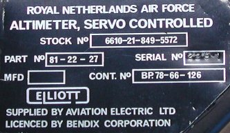
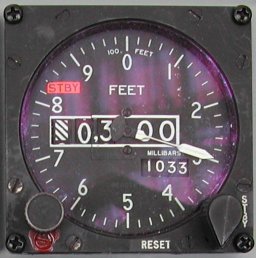
This altimeter has one socket on the rear side, its mating connector is MS 24266-R16T-24-SN. The indicator needs a power supply
of 115 Volt 400 Hz. The control of the needle and the drum counter is realized by a synchro. The setting knob is mechanically
connected to the indicator, but it also rotates a potentiometer of which the connections are available on separate pins. Finally,
the instrument has light sources to illuminate the dial in white and in red light. Although the socket on the altimeter has 24
pins, we do not need too worry much, as several pins are not used or not needed for our purpose.
For example, the coil connected to pins 7 and 10 need 28V DC to de-activate the servo motor ... uhmmm, we want to activate
the motor don't we? Pin 13 is used to electrically reset the altimeter, maybe that pin is not needed either. So, here are the pins
that we really need to get the altimeter working.
|
|
According to the documentation, the 28V power supply for the vibrator, connected to pins 20 and 21, is only needed to decrease
the friction in the mechanism when the indicator is operating in pneumatic mode. If you "tap" on de glass of the altimeter
(when not electrically connected) you may see the needle move a little, and settle on the correct barometric pressure. The
actual incorrect indication is caused by mechanical friction in the instrument. The "tap" overcomes the friction, causing the
small movement to the correct indication. The vibrator acts as a "tapping source". If you want a really accurate indication
while the pit is "off" (the altimeter is not electrically controlled), you need a 28 Volt DC power supply capable of delivering
approximately 100 mA continuous ...
Testing the lighting of the altimeter is easy. Just connect a power supply of +5 Volt AC or DC to pin 4 for red lighting, or
connect pin 6 for white lighting. In both cases pin 5 is the GND connection.
It is obvious that we can not drive such a large instrument with all those mechanical parts using a simple output stage at
+/- 5 Volts, like I used to control the HYD PRESS indicators. So, the first question is: "how to get
a power supply of 115 Volt at 400 Hz"?
The principle is simple: DC voltage in, AC voltage out. The circuit defines the frequency, and they are very common if
you want to go from either 12 or 24 Volts to 120 or 230 Volt AC 50 Hz. They are called "power inverters". They are much alike
the switching power supplies, and here the difficult part is also the transformer. I hate "difficult" ...
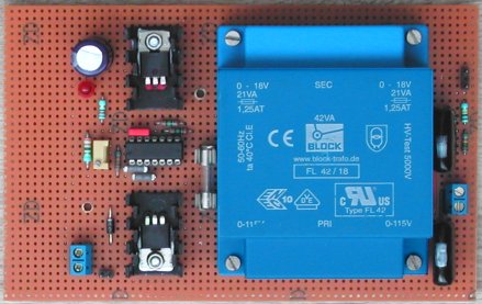
If we can use a common transformer to transform 120 or 230 Volt AC down to 16 Volt for a 13.6 Volt DC power supply, why not
the other way around? Put 16 Volt AC on the "16V" connection tabs of the transformer and get 120 or 230 Volt AC from the
other pins! Now, this is at 50 Hz. But we need 400 Hz ... Maybe you have seen the circuit board of a light bulb controlled
by the output of your audio amplifier. It is a tiny transformer with two coils. One coil to connect to the amplifier speaker
output, the other coil connects to the control circuit to turn on and off the light bulb at a certain adjustable threshold.
Those transformers have an iron core, just like our common power transformers. So, my question is whether a 50 Hz power
transformer could also be used at 400 Hertz? I think the answer to that question is "yes"!
A 400 Hz signal is easy to create using one cheap IC. However, the output of that IC can not drive the coil of a power
transformer directly; we need a power output stage. As 400 Hertz is an "audio frequency", and the transformer is a coil
similar the coil of a loudspeaker, why not use a simple audio speaker amplifier to drive the transformer? It is worth
a try ... the coil of a transformer really acts as a coil (inductance), whereas the coil of a speaker is more like a resistive
load.
The altimeter requires at maximum 25 VA from the 115 V 400 Hz power source. This energy must be supplied by the audio amplifier,
so we need an audio amplifier circuit of at least 30 W, as the efficiency will sure be less than 100%! As proof of
concept, a bought the TDA2030 audio amplifier IC which can deliver some 10 W. That is (likely) not enough to drive the
altimeter, but will suffice to show that common power supply transformers can indeed be used at 400 Hz.
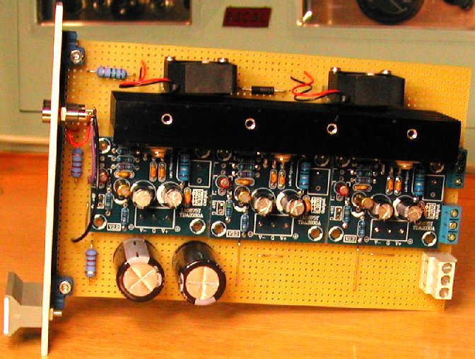
Update
Although I have the TDA2030 on my desk, I am going to try another design first. It uses just a common CMOS CD4047 IC, two
MOSFETs and a common transformer. Just one of the FETs is switched on at any moment. The nice thing about a MOSFET
is that is has a very low ON resistance, thus very little dissipation. Nevertheless, I have built the
circuit on perforated board and used small heat sinks. Better have one now, than adding one later (and Murphy will say
that there is not enough space to put the heat sink on the PCB)!
mounted on a heat sink!
Final remark
Keep in mind that when you use a (digital) Volt meter, the reading will probably be not accurate! That is because
the Voltmeter is designed to operate at 50 Hz, and will probably indicate a too low value at higher frequencies. Our voltage
has a frequency of 400 Hz ... To make an accurate measurement it is better to use an oscilloscope. Then you can check the sine
wave shape (to determine if more capacitance is needed) and make an accurate measurement of the voltage level. Note that
"115 Volt" is an average level. As the voltage is sinusoidal, you can measure the voltage level at the top of the sine wave.
If you divide that level by 1.4 you have the average voltage level. The correct factor is the square root of 2. The measured
top level for 115 Volt average would be some 162 Volt.
Final Update
Although the presented design with the MOSFETs does work, it is a bit cumbersome, because of the required dedicated and adjustable
DC power supply. While I was working on the ADI, I went back to the initial idea to use an audio amplifier that drives a standard
50 Hz transformer. However, The ADI design does not use a linear amplifier, but a class D amplifier. It works great, so I abandoned
the MOSFET design in favor of the class D amplifier design which is a lot easier (you buy the amplifier ready-built on eBay for
less than 10 Euro), and you do not need a dedicated DC power source. Standard 24V DC is all it needs, and that voltage is most
likely already present in the pit.
No guts, no glory -- so I decided to build a test setup. First I tried to assure that the pinout that I have does actually match the altimeter. The first check was the potmeter connected to pins 22-23-24. That did not reveal readings that I expected, so I got a little worried whether my pinout data would be correct. Next test: the internal illumination of the altimeter. This time more luck! Most altimeters have only one "color" illumination, but on the designated pins I have red or white illumination!
Now the tricky part: connecting the 115V AC 400 Hz. I reasoned "other people dismantle the beautiful mechanics to convert the altimeter driven by a stepper motor", so if something goes horribly wrong I still have that option. But I rather have an original instrument working, so a bit nervous I wired the 115V AC.
Now ..., how to drive the altimeter? I happen to have a synchro with a 115V AC rotor, once bought on a amateur radio flea-market. I connected the rotor of that synchro also to the 115V AC power, and the three stator coils of that synchro are connected to the input pins 17-18-19 of the altimeter. OK, ready for a test!
Switch on the 115V AC ... the orange STBY flag disappears! The barometric pressure setpoint (left knob) is still functional,
and the STBY / RESET knob at the right side is also working! When I move that spring-loaded knob briefly
to the RESET position the altimeter starts to move to some setpoint, probably the setpoint indicated by the
axis position of the test-drive synchro. Moving the knob briefly to the STBY position the orange STBY flag
appears and the altimeter indication reverts to the barometric pressure indication. So, that seems to work just fine.
Again moving the knob briefly to the RESET position. The orange STBY flag disappears and the altimeter runs
to the setpoint dictated by the connected test-drive synchro. So, everything seems OK. Now I rotate the axis of the test-drive
synchro ... the altimeter indication reacts very "strong". I discovered that minute movements of the axis of the test-drive
synchro results in significant rotation of the altimeter pointer. To say the least, it is very sensitive!
So, slowly rotating the axis of the test-drive synchro, can can get the altimeter up to approximately 12.000 feet. But I
found out that as the higher the "altitude" gets, the more difficulty the pointer gets to move passing the "800 feet" indication.
It seems that there is some friction inside the instrument at that point. If I rotate the axis too fast, it seems that the
altimeter "looses track". Then the orange STBY flag appears and the altimeter returns to the starting altitude indication at a
fixed speed. I guess that at "higher altitudes" the bellows inside the altimeter indicate a larger deviation between actual
pressure (still on the ground), while the altitude pressure indication by the test-drive synchro tells something different.
Clearly this is not the behavior I want to see happen in the pit.
I was hoping that I might use the vibrator to help overcome that friction. But that is not an option, because after I connected
24V DC to pins 20-21, the vibrator makes an annoying "tick-tick" sound, and it only works in "STBY" mode. So, it is of
no use to overcome friction while driven by the synchro signals.
Something else ...
I have wondered many times how one single synchro can set the altimeter to the correct altitude reading. As the altitude computer
(or air data computer or some other smart device) generates the signals for the synchro, I assumed that the device will keep
track of how many turns the indicator has made. However, at power up the initial position is not known. I explained that by
assuming that the pilot sets the altimeter to the correct height which is a known constant for any air force base. The tower
communicates the actual barometric pressure, and all the pilot has to do is adjust the altimeter to the actual barometric
pressure setting.
But then I read in some documentation that the synchro is used for the correct (fine) height indication and that the bellows
inside the altimeter are used for coarse height indication. The synchro has a range of some 4000 ft. If that is the case it will
be almost impossible to get a working altimeter (unless you can also generate the barometric pressure at say 30000 ft
accurately ...).
Here is the text I read.
3.5.10 Altitude deviation. The altimeter shall be capable of accepting electrical signals which differ from
the pneumatic mode by as much as 2,000 feet up to 3,000 feet pneumatic indication and linearly increasing to 3,500 feet at 30,000
feet pneumatic indication over the temperature range of -54 degrees to +71 degrees Celsius (-65 degrees to +160 degrees Fahrenheit)
and input power range specified herein. Altitude deviation signals shall not affect the standby scale error by more than 15 feet
immediately after application. The altimeter shall meet the scale error requirements within 2 hours after signal application.
Nice to know information: one 360 degree rotation of the axis of the test-drive synchro is exactly 10,000 feet.
I got the following information from "Raven", and it is very useful to know.
So here are a couple of points regarding the operation of the servo altimeter. It is designed to normally operate in the servo
mode where it receives information from the air data computer (ADC). The computer has corrected the static pressure reading for
temperature and more importantly, position error.
Position error occurs as a result of the speed and shape of the aircraft affecting the "bubble" of static pressure around the aircraft. The greatest difference between the real and perceived static pressure is in the transonic region and it increases until mach 1. After that it begins to drop back off, but never equals the ambient static pressure. Each aircraft will have a correction chart for position error for both airspeed and altitude in the flight manual as it is different for each aircraft type. For the Voodoo, at about .098 mach, the difference in altitude is approximately 3200 feet. The colored text above ("3.5.10 Altitude deviation") quoted in the altimeter specs regarding the altimeter being able to register a difference between the normal and standby modes refers to it being able to tolerate and indicate the differences as a result of position error.
When the altimeter operates in the normal mode, all altitude information comes from the ADC. If the ADC fails, the altimeter will automatically revert to standby mode and the orange STBY flag will come into view. On some models of altimeter, when it is in the standby mode, an internal altimeter vibrator (usually 28V DC) will come on to help remove any friction error in the mechanical works. You can of course select the standby mode any time the reading is suspect from the ADC.
When flying and you are climbing, upon reaching 18,000 feet, you must set the baro to 29.92 inch Hg (1013 mb)". This ensures that all aircraft above 18,000 feet are using the same altimeter setting and thus, the term flight level is used, for example FL250 (25,000 feet). You also must set the altimeter back from 29.92 (1013) to the local pressure setting upon descending back through 18,000 feet. When you set your altimeter on the ground, you are establishing the reference setting for the altimeter, and there will be no difference between the ADC and the standby mode reading. The position error below 18,000 feet will also be negligible as ICAO specifies all aircraft must not exceed 250 KIAS below 18,000 feet unless emergency or military operational requirements dictate otherwise.
We need a 400 Hz excitation signal, which is derived from the 115 Volt AC input power. That signal is also used to generate the signals for the three stator coils of the altimeter synchro. The stator sine waves are always in phase with the rotor sine wave, as they are derived from the 115 Volt AC 400 Hz power supply. The "position" (read: rotated angle) of the synchro is defined by the amplitude of the three stator signals. These amplitudes have the 0 / 120 / 240 degree "phase shift" relation to each other. By varying the amplitudes of the stator sine waves you set the synchro to a specific angle.
Very useful is pin 15 "external synchro excitation 26V, 400 Hz". When the altimeter is in stand-by mode there is no voltage
present on this pin, but when the altimeter is in servo mode almost 26V AC 400 Hz is present on this pin. This is probably used
for the synchro in the altitude computer and must be in phase with the 115V 400 Hz power supply on pin 2. Pin 3 is the common
connection for the 115 Volt 400 Hz power supply and pin 15 for the external synchro.
I repeated my tests, but now I did not use the test-drive synchro at 115V AC (same power as applied to the altimeter), but I used
a 26V test-drive synchro, rotor connected to pin 15 and pin 3. When the altimeter is switched to servo mode, the test-drive synchro
is working. First I set the baro preset knob to 1019 mb (the altitude then indicated 00000). Rotating the test-drive synchro
"downward", I can get the altitude down to 63500. Rotating the synchro "upward", I can get the altitude up to 35600 !
I guess that means the altimeter can be used without modification up to 35000 feet.
The voltage on pin 15 can be used to electronically generate the signals for the synchro in the altimeter. Any (small) phase shift
between the 115V AC and the 26V output is cancelled out, because the altimeter's internal electronics also use that 26V AC.
The final design took 3 attempts. It is simply too much work (and time) to solder a test board, although that is the most flexible
way as it is easy to make corrections. Instead, I made my design straight away in Eagle and placed an order at ITEAD for making
the PCB. The drawback is that you have to order a minimum of 10 PCB, but at a total cost of approximately 5 Euro per PCB, it is
very competitive with "local" PCB manufacturers who charge 70 Euro for 1 PCB! My first design "included" a big mistake, so lesson
learned: always double check! Design #2 did work, but it needed 3 simple patches. Not the way to go if you want to sell the PCB.
Further, as a result of removing the bellows from the altimeter, the indication was very "nervous". Just very small fluctuations
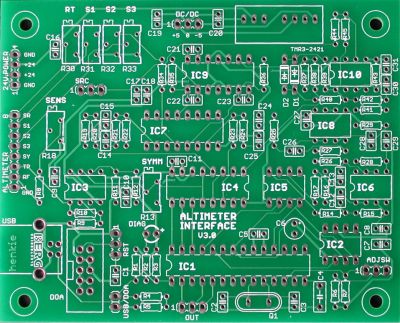
of the VCA control signals caused the needle pointer of the altimeter to change. Therefore, I decided to make PCB #3. This is the
final version. No patches needed, and I added 3 Sallen-Key filters in the control voltage to the VCAs. Now, the indication is
fluent, and as a nice side effect of the filters, the indication update is not "jumping" to the new setpoint, but also nicely
damped. I also improved the generation of the opposite phase signal and added a local 400 Hz sine wave oscillator. This oscillator
is not needed for the altimeter functionality, but may be useful for another application.
The PCB has an on-board small DC/DC converter that generates the -5V and +5V for the logic and analog circuits. This design only
needs +24V DC power supply, and all required connections (power supply and altimeter) are at one side of the PCB. The USB or DOA
connection is also at that side. At the opposite side you can connect two push-buttons. One push-button enables you to set the
altimeter to the correct altitude indication, the other push-button set the update "direction": increase or decrease the altitude
setting. When you keep the update button pressed, the update is at first in small steps, but after 10 steps the update goes faster
and after 10 faster updates the update even goes much faster, but also with bigger "step size".
Power supplies
The PCB only needs +24V DC if you use the on-board DC/DC converter. Perhaps you have a (clean) +5V and -5V supply voltage in the
cockpit available. In that case you can omit the expensive DC/DC converter (22 Euros), and connect +/-5V to the DC/DC 3-pin
input header.
The altimeter requires 115V AC 400 Hz power supply. In the end, I am using the design as described on the ADI page. This design
only needs +24V DC and uses a cheap class-D amplifier (on eBay for less than 20 Euro). A simple OpAmp generates a 400 Hz sine
wave which is amplified by the class-D amplifier. The output of the amplifier drives the secondary 18V coils of a
transformer, and at the primary coils (used as output) is a nice 115V AC 400 Hz power source. To improve the shape of
the sine wave a 470 nF 400V capacitor is connected in parallel with the output.
Amplifiers
The Altimeter Interface only generates the signals required for the synchro stator coils, but these signals are not capable of
driving the stator coils. The 3 signals must be amplified. The easiest (and in this case probably also the cheapest way) is
using simple mono amplifier kits from eBay. They cost some 5 Euro and contain a small PCB, the LM1875 amplifier IC and all
other components needed to build a single channel 20W amplifier. All that you need to add is an appropriate heat sink. Even the
silicone insulation pad for the LM1875 is included in the kit. To drive the altimeter you need 3 kits.
These amplifiers require a symmetrical power supply. Any symmetrical +/-18 .. 24V DC will be fine.
The experimenter board serves as a "carrier" for the 3 amplifier PCBs and the heat sink. As the heat sink is rather small and I prefer to keep electronics cool, I mounted two tiny fans on top of the heat sink. On the front panel are 2 LEDs that indicate that +24V DC and -24V DC is present. At the rear side are 3 3-terminal connection blocks. One is for -24/GND/+24V DC power supply, the second connection block is for the 3 stator input signals (from the Altimeter Interface PCB), and the third connection block is the 3 stator output signals (connected to the X/Y/Z inputs of the altimeter indicator).