Tricky rotary switch ... Do It Yourself solution
| KY58 Secure Voice panel Tricky rotary switch ... Do It Yourself solution |
|
The KY58 panel is not a very important panel in the simulator, because there is not much
information available. The information of this "Secure Voice" panel is classified "top secret". What you can do with the
FILL connector is not clear either. We can only guess, but the functionality of this panel is,
obviously, not supported in BMS. However, it is a panel in the pit. And there are other panels in the pit
that are more or less "eye candy", so I try to build this panel as good as possible.
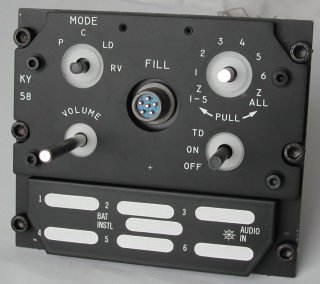
On the KY58 panel are the following components.
The 8-position rotary switch has a special mechanical functionality (besides 36° steps). The leftmost and rightmost position are locked-out and can only be selected after you pull the knob. Chances getting the real rotary switch is slim, and if one becomes available you will be fishing with many other chaps in the same pond. Thus, the price of this item is "what you can afford". I tried a DIY solution which is way cheaper, and fairly easy to do.
Parts explanation
A - mounting backplate
B - metal plate
C - metal plate
D - shaft
E - bushing
F - ring
G - lock plate
H - spring
L - self-locking M3 nut
N - M3 nut
P - setscrew
R - distance rings
S - M3 screw
T - rubber ring
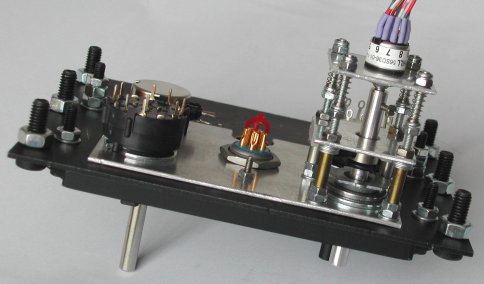
The drawing shows the solution for the rotary switch knob on the KY58. The assembly is mounted on the panel backplate, or on a
separate (small) aluminum plate {A}. The shaft of the rotary switch {D} must slide through a bushing {E}. This bushing is mounted
on the metal backplate {A}. I got the bushing from an old potmeter, which also gives you the 6 mm shaft, because you need to make
the shaft of the switch longer. At 4 corners of an imaginary square surrounding the knob you mount 4 countersunk M3 screws of
sufficient length {S} on the metal plate {A}. The screws are fixed mounted on the backplate with nuts {N}. In my construction the
length of the 4 screws is 50 mm.
At a distance of approximately 20 to 25 mm is a small square aluminum plate {B} which is fixed mounted using nuts {N} on the four
long screws. In the metal plate {B} is a hole of some 7 to 8 mm so that the shaft rotates freely. On the shaft {D} is a snug
fitting "ring" {F}. This ring has a thickness of approximately 6 to 10 mm and has a setscrew, so you can fixed mount it on the
shaft. The distance between metal plate {A} and metal plate {B} minus the thickness of the ring {F} defines the distance you can
pull the knob on the panel. The 2 pink rings {T}, behind the bushing and against the front side of metal plate {B} are thin rubber
rings (a grommet cut in half). They prevent the metal "clunk" sound when you pull the ring {F} against the metal plate {A} or when
the shaft is pulled back by the springs against metal plate {B}.
On a third small square metal plate {C} is the rotary switch mounted. If you can pull a knob, it should of course retract
automatically to its initial position when you let go. So, this metal plate {C} fits "loosely" on the 4 long screws, so that the
metal plate can slide smooth over the screws (see Note below). The shaft of the rotary switch is fixed mounted to the shaft {D}.
On the 4 long screws are little (identical) springs {H}. At the end of the long screws are self-locking M3 nuts {L}.
As you pull the shaft {D}, the ring {F} moves between the plates {A} and {B}, and the plate {C} with the rotary switch moves too.
If you release the knob, the springs will pull the knob back to its rest position. I got 4 identical springs removed from four
ballpoints.
The rotary switch on the KY58 has 8 positions (at 36 degree step angle), but the leftmost and rightmost switch position can only be selected if the knob is pulled first. The 6 in-between positions can be selected by simply rotating the knob. The leftmost and rightmost locked-out positions are realized using the ring {F} and a "lock plate" {G}. The lock plate {G} is mounted on the lower two long screws (but can be at any other 2 screws). The ring {F} (and in it the shaft {D}) can rotate freely "over / in" the lock plate {G} as long as the setscrew {P} of ring {F} is not blocked by the lock plate. To rotate the switch to the leftmost or rightmost position, you must pull the shaft {D} so that the setscrew {P} moves towards the front, past the lock plate {G}. The ring {F} with the setscrew {P} serves two functions: pull/push travel distance and lock-out positions. The detailed drawing shows a front view of the shaft {D}, ring {F}, setscrew {P} and the locking plate {G}. The 6 "normal" positions of the KY58 rotary switch (with step angle of 36 degrees) span 180 degrees of rotation, from the drawn position at 3 'o clock to the position at 9 'o clock. The switch positions at approximately 8 'o clock and 4 'o clock can only be reached after the shaft is pulled so that the setscrew can move in front of the locking plate. I made the locking plate of "plexiglass" (perspex). I did not have perspex of some 8 mm thickness, so I used two pieces of 4 mm thickness. As the rubber ring {T} against the plate {B} takes 2 mm, I added the rings {R} to position the locking plate.
Note. You can use a file and sandpaper to remove the threading of the 4 long screws over the travel distance of the metal
plate {C}. There are a few things that need special attention. First, if the shaft of the switch or potmeter is not long enough,
you need to extend its length with another shaft. You might want to do this anyway, because an (old) potmeter can be a donor for
the shaft and the bushing to slide the shaft through. The tricky part here is that the extended shaft and the shaft of the switch
or potmeter must be perfectly centered and aligned. A lathe is the perfect tool to accomplish this!
The other important thing is that the center of the bushing and the center of the shaft of the switch or potmeter must be aligned.
By drilling the holes in metal plate {A} and/or {C} a little larger you have "play" to get the alignment good.
|
|
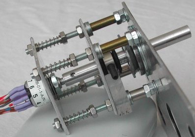
| Rotary switch at leftmost free position [1] |
Rotary switch at left locked-out position [Z 1-5] Note the shifted (pulled) shaft in the locked-out position. |
The nuts at the end of the 4 screws define the shaft position for the free switchable positions. The nuts between the 2 rear plates set the "pre-tension" of the springs. The 4 nuts at the end and the 4 "pre-tension" nuts should be self-locking, but this picture shows the "prototype", so it must be easy to disassemble.
|
|
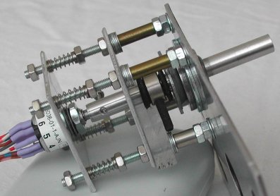
As you can see, the normal M3 nuts are replaced by self-locking M3 nuts. The shaft rotates nicely, and pulling the shaft for the
leftmost and rightmost position works great. My fear that the assembly would not "retract" smoothly has not come true. Just in
case, I already had a "fallback" idea. As an option, I could file the M3 threading off the screw over the length that the metal
plate with the rotary switch must slide. But it turned out it is not necessary ... I guess the force of the four spring is OK.
Too late I learned that the locked-out positions are momentary, thus when the knob is pulled and
rotated to the leftmost or rightmost position, the knob will return to position [1] or [6] "automatically". I do not have the
required springs installed, but using the setscrew and two small springs, it should be possible to realize the momentary action.