| CP/M system from D|I|G|I|T|A|L ! | VT180 |
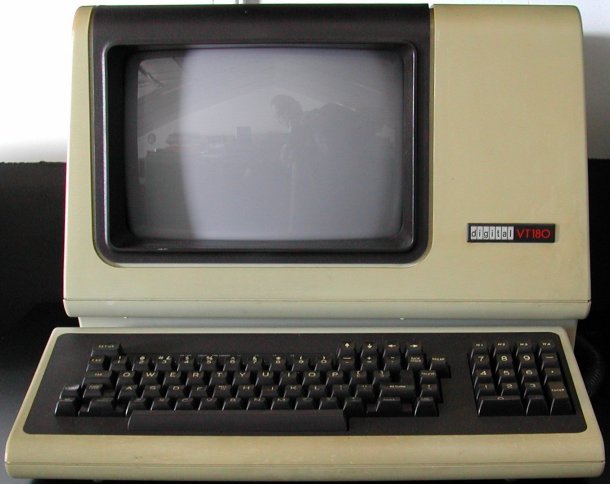
As you can see, the VT180, also know as the "Robin" looks very similar to a "standard" VT100 terminal. In fact it is! You can buy an upgrade kit for your VT100 which consists of (among others) a big circuit board with RAM, EPROM and an Intel 8085 microprocessor, turning the VT100 into a VT180 computer system capable of running the CP/M operating system.
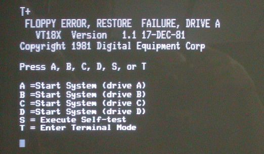
The first time that I powered the VT180 it was not connected to an RX180 floppy disk drive unit, because I do not have the BC29K connection cable. That cable connects via a 37-pin sub-D connector to the RX180 unit which has a 25-pin sub-D connector.
If you enter the "S" key of the keyboard to execute the Self-test, you get the same output again as long as no floppy disk unit is connected.
I have not tried entering "T". I have several VT100 and more modern VT-series terminals, so I really want to use this VT180
only as a CP/M computer system.
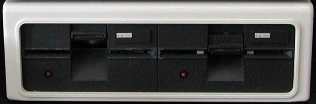
The CP/M Operating System is a "DOS", where the "D" stands for "disk". Thus, you need some disk subsystem to run CP/M. D|I|G|I|T|A|L supplied the RX180. The RX180 is a small box that contains two 5.25 inch floppy disk drives and a power supply. On the rear side are two 25-pin female sub-D connectors. One is used to connect to the VT180, the other can be used to connect to a second RX180 unit. Yup, you can have up to four floppy disk drives connected to the VT180!
The connection cable from the VT180 to the first floppy drive unit (RX180) is a BC29K.
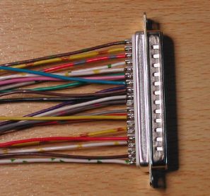
The BC29K has at the VT180 connection side a DC37-pin sub-D connector and at the RX180 connection side a DB25-pin sub-D connector.
That makes it obvious that there is probably not a 1:1 pin connection between the two connectors. And there isn't.
After some googling, I found Will Kranz's website and the VT180 Technical Manual, EK-VT18X-TM-001_VT180_Technical_Man_Feb83.pdf.
On page 3-37 is a table of the 37-pin connector with the allocated pins and which signals they carry. Very helpful to make a cable,
but it was until I found an original BC29K that I was sure it was all correct. The "not used" in the table means that the DC37 male
connector of the cable does *not* have a pin!
| 37-pin sub-D connector | 25-pin sub-D connector | ||
|---|---|---|---|
| pin number | signal name | mnemonic | pin number |
| 1 | not used | GND | |
| 2 | not used | N/U | |
| 3 | not used | GND | |
| 4 | not used | N/U | |
| 5 | not used | GND | |
| 6 | Select 3 | SEL3 L | 1 |
| 7 | not used | GND | |
| 8 | Index | INDEX L | 2 |
| 9 | Ground | GND | 15 |
| 10 | Select 0 | SEL0 L | 3 |
| 11 | not used | GND | |
| 12 | Select 1 | SEL1 L | 4 |
| 13 | not used | GND | |
| 14 | Select 2 | SEL2 L | 5 |
| 15 | not used | GND | |
| 16 | Motor on | MOTOR ON L | 6 |
| 17 | not used | GND | |
| 18 | Direction | DIR L | 7 |
| 19 | Ground | GND | 20 |
| 20 | Step | STEP L | 8 |
| 21 | Ground | GND | 21 |
| 22 | Write data | WRT DATA L | 9 |
| 23 | Ground | GND | 22 |
| 24 | Write gate | WG L | 10 |
| 25 | Ground | GND | 23 |
| 26 | Track 00 | TK00 L | 11 |
| 27 | Ground | GND | 24 |
| 28 | Write protect | WRT PRT L | 12 |
| 29 | not used | GND | |
| 30 | Read data | RD DATA L | 13 |
| 31 | Ground | GND | 25 |
| 32 | not used | N/U | |
| 33 | not used | GND | |
| 34 | Drive ready | READY L | 16 |
| 35 | not used | ||
| 36 | not used | ||
| 37 | not used | ||
The 37-pin sub-D on the VT180 rear side panel is female, and the 25-pin sub-D on the RX180 rear side is also female. Thus, the
connection cable has at one side a 37-pin sub-D male connector and at the other side a 25-pin sub-D male connector.
With this table the soldering of a cable is not much work, although ... DEC uses a shielded cable, so I figured I should do too.
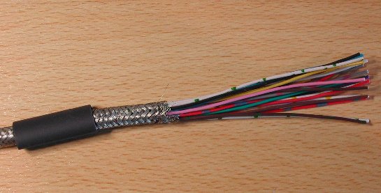
But where to get a shielded cable with that number of wires? I decided to make my own version of a shielded cable. I do
have shielded cable with 16 wires, so I cut 2 pieces of identical length and then stripped the outer insulation and slided the
braided shielding of the cable. That braided insulation will be put back, so avoid damage to it.
 |
 |
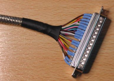 |
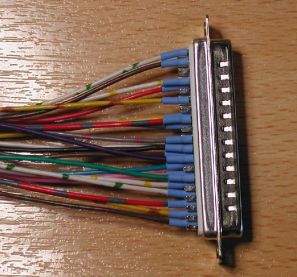
| wires soldered to DC-37 pins | heat shrink tubing on soldered pins | braided shielding over wire bundle |
|---|
Then I soldered the 21 wires to the 37-pin sub-D connector. I used shrink tubing on each soldered pin to support the wire. Now comes the trick. The other side of the wires is tied together with a piece of waxed lacing, but a small piece of adhesive tape will probably also work. Now you push the braided shielding piece by piece together, thus making the diameter a lot bigger. Through this "widened" braided shielding you can slide the bundle of 21 wires until the bundle comes out of the braided shielding at the other end. Slide your fingers over the braided shielding so that it is more or less snug (not too snug) over the bundle of wires. You can put two pieces of shrink tubing over the braided shielding so that you can (later) make a "seal" as finishing touch. If you do not slide the braided shielding too snug over the wire bundle, you still have a few inches of loose wires at the other end. Now you can solder the other end of all wires to the 25-pin sub-D connector (do not forget the heat shrink tubing). When that is done you can slide the braided shielding nicely "distributed" over the wire bundle and shrink the tubing at both ends near the connector. If you prefer, you can put a hood on the connectors.
 |
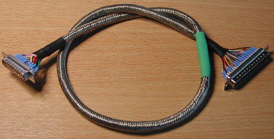 |
| wires at the opposite end | wires soldered to DB-25 pins, shielding "stretched" and finished with tubing |
|---|
Keeping fingers crossed ... the home-made BC29K connects the RX180 to the VT180.
As described in the VT180 documentation, the mains power cable is connected to the RX180 unit, and an out-going power cable
connects power to the VT180. The POWER switch of the VT180 is set to "ON"
(permanently). The mains power switch on top of the RX180 unit becomes the power off/on switch for the system. So, you do
not have to reach for the power switch on the rear side of the VT180, but conveniently can flip the power switch on the top
of the floppy drive unit.
| Back to top |