| SYSTEM BOXES | BA11-VA |
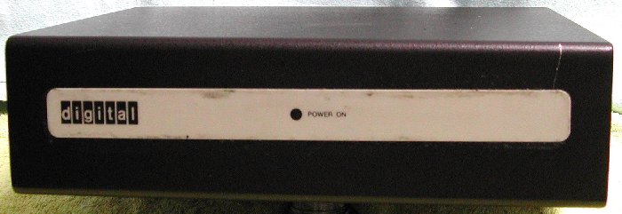
D|I|G|I|T|A|L made several housings to hold their systems. First, there were the "BA11" boxes for the PDP-11. Of course, there were boxes for the PDP-8 and earlier systems, but I am not familiar with those machines. The suffix letter following the BA11 designation defined the box for the early types. The more modern types used for QBUS systems were defined by the letters BA followed by a number.
 The box is opened by removing the 2 screws at the left and right side of the box. You must do this, because you have to check
if the AC input voltage selection switches are set correct for your mains outlet voltage. Note that there are two
switches which must be set to the same voltage setting, 115 or 230 Volt. One switch sets the AC input voltage for the power
supply and is located on the power supply board, the other switch sets the supply voltage for the internal fan and is located
on top of the metal housing of the power supply AC filter, AC input socket and AC fuse holder. After you set the switches,
you should affix the appropriate voltage decal to the back of the BA11-VA, according to the "BA11-VA Configuration Guide"
(EK-BA11V-RG-001). Probably that label is not anymore with your box. If you like, you can make a label
and glue that to the back of the box as a reminder for yourself.
The box is opened by removing the 2 screws at the left and right side of the box. You must do this, because you have to check
if the AC input voltage selection switches are set correct for your mains outlet voltage. Note that there are two
switches which must be set to the same voltage setting, 115 or 230 Volt. One switch sets the AC input voltage for the power
supply and is located on the power supply board, the other switch sets the supply voltage for the internal fan and is located
on top of the metal housing of the power supply AC filter, AC input socket and AC fuse holder. After you set the switches,
you should affix the appropriate voltage decal to the back of the BA11-VA, according to the "BA11-VA Configuration Guide"
(EK-BA11V-RG-001). Probably that label is not anymore with your box. If you like, you can make a label
and glue that to the back of the box as a reminder for yourself.
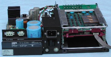
At the rear side are, besides the AC power input socket, two AMP sockets for remote restart of the system, and auxiliary
power supply (+5V and +12V), see the pictures. The Remote Restart (2 pins) socket can be used to connect a remote switch to
restart the program when the BA11-VA is switched on.
|
 The auxiliary power (3 pins) socket is used to connect +12 VDC and +5 VDC and ground to an external option. The maximum DC power including auxiliary input is +5 VDC @ 5.6 A and +12 VDC @ 1.6 A. You must make a power calculation of the installed modules in the BA11-VA box to know the maximum load that can be connected to the auxiliary power socket. |
Installation of the PDP-11 modules
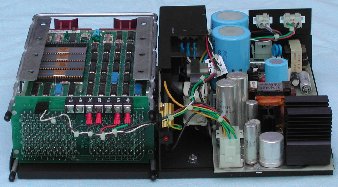
 The card cage can hold four dual-height QBUS modules. The access to the card cage is possible when the
top cover is installed. A small access cover is at the rear side and is removed by turning the two locking screws a quarter
turn counterclockwise. Looking at the rear side of the BA11-VA box and the opening to the card cage at the right hand side,
the top slot of the LSI-11 4-slot backplane is dedicated for the LSI-11 (PDP-11) processor module. The three remaining slots
can be used for memory and peripheral interface modules.
The card cage can hold four dual-height QBUS modules. The access to the card cage is possible when the
top cover is installed. A small access cover is at the rear side and is removed by turning the two locking screws a quarter
turn counterclockwise. Looking at the rear side of the BA11-VA box and the opening to the card cage at the right hand side,
the top slot of the LSI-11 4-slot backplane is dedicated for the LSI-11 (PDP-11) processor module. The three remaining slots
can be used for memory and peripheral interface modules.
To configure the BA11-VA box, consult the Microcomputer Handbook Series for dual-height processor module configuration and
the memory and peripheral handbook for dual-height memory and option module configurations. The BA11-VA box will accept one
double-height processor module and up to 3 double-height option modules.
The BA11-VA box does not generate a line time clock. A 60 Hz XTAL clock may be obtained from the multi-function memory option
MXV11.
At the left of the module access cover, below the AC power switch, is a chassis ground screw. The chassis ground screw is
used to ground LSI-11 serial line interface cables to the BA11-VA box. This screw provides the chassis ground connection needed
for correct operation.
My "minimalist" PDP-11 system
I have an LSI-11/2 processor (M7270) installed in the upper slot in my BA11-VA box.
To have a complete PDP-11 system you need at least some memory and a serial line to connect the system console. As the BA11-VA
box only has 4 slots, you must make a good choice of the available options, if you want to build a complete system without the
use of an additional expansion box.
|
|
| Rear view on BA11-VA (cover removed) | Front view on BA11-VA (cover removed) |
|---|
I installed in the second slot the MXV11 option module, M8047. This module is capable of generating the line time clock, has
two serial line interfaces and RAM. The MXV11-AA
    @000000/177777
    000002/177777
    000004/177777
    000006/177777
    000010/177777
    000012/177777
    @077774/000000
    077776/000000
    100000/?
    @
|
Here you see a short ODT dialog. Memory location 000000 is opened by entering 6 zeroes followed by a slash. ODT immediately prints the contents of location 000000 which is all ones (177777) in this case. Next, the LF (Ctrl-J) is entered and ODT will open the next word location, 000002. This is repeated a few times, and at location 000012 the CR is entered, closing the memory access. ODT prints the "@" prompt on the next line. To check the total installed memory on this MXV11 (16k words, 32 kbytes), I opened memory location 077774. The contents is 000000. Entering Ctrl-J opens the next location, 077776. Ctrl-J again would access the first location after 16k words, octal 100000. There is no RAM at that location, and ODT prints a "?" followed by the "@" prompt on the next line. |
If you do not have a SCSI module or RD5x hard disk (the other parts needed, M7555 or SCSI hard disk are easy to get), there is yet an other method for external storage. As described, the MXV11 option includes two serial line interfaces. One interface is factory configured at address 177560, which is the CSR for the system console. Looking at the rear side of the BA11-VA box and the opening to the card cage at the right hand side, with the MXV11 module installed, the connector for the system console is at the right side, see the "Rear view on BA11-VA (cover removed)" picture above. The small ribbon cable is the connection to the system console. You have to make a cable to connect the 10-pin BERG header to a 25-pin or 9-pin D-SUB connector to hook the PC serial port to the MXV11.
| Connector pins of MXV11 serial ports (view towards front edge of module) |
BERG header pin # | signal (from MXV11) | 9-pin D-SUB (to PC) pin # |
|---|---|---|---|
 |
1 | UART clock | nc |
| 2 | GND | 5 | |
| 3 | XMIT data + | 2 | |
| 4 | XMIT data - | 5 | |
| 5 | GND | 5 | |
| 6 | key | nc | |
| 7 | RX data - | 5 | |
| 8 | RX data + | 3 | |
| 9 | GND | 5 | |
| 10 | +12 Volt | nc |
Booting the LSI-11/2 from a simulated TU58 tape
Suppose you can load de bootstrap code for the TU58 device, and have a real TU58 connected to the second serial interface.
If the loaded TU58 cartridge has a bootable system, you can run your PDP-11 from it. However, the continuous tape re-positioning
would severely impact the "system performance". But there is a TU58 emulator available on the internet. The emulator does
not need to re-position the "tape". Check out
Will Kranz' DECtape II, TU58 emulation page,
and the page of Don North, TU58 XXDP Image Files , the
emulator that I actually use to emulate a TU58.
012701 176500 012702 176504 010100 005212 105712 100376 006300 001005 005012 012700 000004 005761 000002 042700 000020 010062 000002 001362 005003 105711 100376 116123 000002 022703 001000 101371 005007 |
The bootstrap code listed at the left must be loaded via ODT starting at address 001000 (octal). If you have not made any errors,
the last word entered should be at location 001070. It is a jump to address 000000, the start of the (just read from tape) DD: device
driver for the TU58 device unit #0.
Do the following steps to load the bootstrap code using ODT using a terminal emulation program.
|
pdp11.log opened Fri Jan 18 22:22:56 1980 177777\? @1000/177777 12701 001002/177777 176500 001004/177777 12702 001006/177777 176504 001010/177777 10100 001012/177777 5212 001014/177777 105712 001016/177777 100376 001020/177777 6300 001022/177777 1005 001024/177777 5012 001026/177777 12700 001030/177777 4 001032/177777 5761 001034/177777 2 001036/177777 42700 001040/177777 20 001042/177777 10062 001044/177777 2 001046/177777 1362 001050/177777 5003 001052/177777 105711 001054/177777 100376 001056/177777 116123 001060/177777 2 001062/177777 22703 001064/177777 1000 001066/177777 101371 001070/177777 5007 001072/177777 @1000G ?BOOT-U-I/O error 000720 @1000G ?MON-F-Power fail halt 052052 @1000G ?BOOT-U-I/O error 000720 @1000G RT-11FB (S) V05.04 B ?KMON-F-File not found DK:STARTF.COM .dir RT11FB.SYS 101 11-Apr-95 DL .SYS 5 11-Apr-95 DY .SYS 4 11-Apr-95 DD .SYS 5 11-Apr-95 RK .SYS 3 11-Apr-95 SWAP .SYS 27 16-May-90 RESORC.SAV 25 16-May-90 DIR .SAV 19 16-May-90 DUP .SAV 49 16-May-90 PIP .SAV 30 16-May-90 VBGEXE.SAV 16 20-Dec-85 PACMAN.SAV 28 15-Dec-93 ZEMU .SAV 49 STRTRK.SAV 54 21-Nov-96 14 Files, 415 Blocks 89 Free blocks . . |
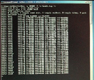
Here you see the output of PDPDB.EXE. It was captured to a log file. When you enter "Ctrl-L" in
PDPDB.EXE all output is written to the file PDPDB.LOG. Entering "Ctrl-L" again stops
logging the output, and "Ctrl-L" again starts logging, any output is appended to the log file. With "Ctrl-U" the bootstrap code is uploaded. Entering 1000G starts the bootstrap, but as you can see that was not successful as I got the ?BOOT-U-I/O error message. Tried 1000G again, but the system hangs. The bootstrap code is probably overwritten, so I switched the BA11-VA off. To my surprise I got the output ?MON-F-Power fail halt! So, one more attempt. but alas ... no good. What now?
I saw that I also got errors reported from the TU58EM program, "bad packets". I wondered ... is the
communication baudrate OK? I assumed that it would default be set to 9600 Baud, just like the console port. Better check that! Lesson learned: with serial communications, setting it up the first time, always check settings, do not assume the setting are correct!
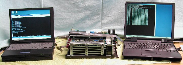
Closing Hyperterm and starting TU58EM again. I start the TU58 emulator with the command entry
Starting the bootstrap code again on the console ... this time no "bad packets" received messages, and after some 10 to 15 seconds the first line is printed.
A few seconds later the rest follows and I have the "dot" promt of RT11. Cool, it works! As you can see, the .dir command lists the contents of the simulated TU58 tape. Any old 486-based PC is fit for the two tasks, a terminal program at 9600 Baud for the system console, and the TU58 emulation program at 38400 Baud. The old PC's also have two old-style serial ports COM1 and COM2, so such an old system is just waiting for a second life! It is not blindingly fast, but it works! |
| ||
|
| |