| DASHER 200 TERMINAL |
|
Introduction
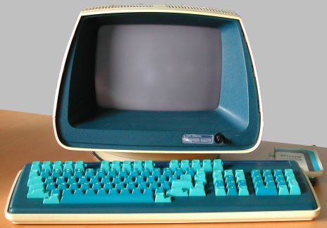
The first "Dasher 200" terminal came with the first system that I picked up, the NOVA 3. I got a second D200 terminal from Geert. The Dasher 200 terminal has a very typical, recognizable shape, and of course the "Data General" blue color. One keyboard has a few keys of which the spring action is gone, so those keys are always "pressed". Definitely repairable.
The Dasher D200 terminal displays standard ASCII characters but has a cursor control and other special feature code set different than other vendors. Later Data General Dasher terminals did have ANSI 1964 support along with the "Data General mode" support.
The keyboard cable connects to the rear side of the base unit (with the CRT) using a rather simple header. The separate wires are
visible. A less fragile connection, for example, a sub-D connector would have been a better choice.
Description
The Dasher 200 terminal consists of a separate keyboard and a base unit. In the base unit is the screen, electronics and the power
supply. Pretty standard. Not so standard is the way to open the base unit. To open the base unit, you first remove the
The terminal has the following connections at the rear side.
Keyboard connection
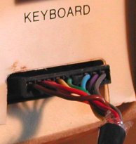
The keyboard is connected to the base unit with a simple 9-pin header. This is probably the minimalistic solution to connect
something. No strain relief, no shielding, no proper hood to handle the cable when you plug it in. OK, at least there is one pin
that serves as a key to prevent wrong plugging it in.
On the other hand, in a normal environment you put the base unit on the desk, put the keyboard in front of it and plug in the cable.
Perhaps we nowadays would have used a tie-wrap as strain relief and protection against not-intended disconnection and bent pins
when a typist gets "too enthousiastic", and gives the keyboard a firm whack.
Terminal connection
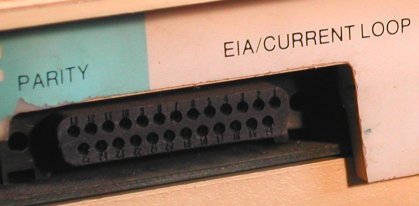
The terminal connects to the computer (or modem) with a standard DB-25 female connector. On this connector are pins for EIA
("RS-232") and for 20mA current loop.
| Left, next to the terminal connection are 8 DIP switches. The left four DIP switches (numbered 1 to 4) set the baudrate. As you can see, there are a few baudrates that would be considered "weird" today. DIP switch 5 and 6 set the parity.
| ||||||||||||||||||||||||||||||||||||||||||||||||||||||||||||||||||||||||||||||||||||||||||||||||||||||||||||||||
Some first-hand information
Sometimes, writing a web page has very nice "side effects". Just a few weeks after I added this page about the Dasher 200 terminal,
I received an email from Peter Simpson. Peter really knows the D200 ... he was on the team that designed the D200!
This is what Peter told me.
Working on the design of the D200 was his first job out of college. He wrote some of the code (see below), and Peter was
responsible for the keyboard electronic design and test. The Data General internal code name was "PEGASUS".
The overriding goal was LOW COST. Data General's existing terminal, the 6053, was big, heavy, and expensive to build.
At the time DG was competing with things like the Lear Siegler ADM-3, which was only a few hundred dollars. The goal of the design
team was to design a full featured CRT terminal for less than the cost of an ADM-3. For that time, the team did some very
innovative stuff.
Due to some of the design choices, the D200 had a few problems.
That was a clever idea (IMHO).
One more tidbit.
There is a not-so-secret command to download a Motorola S1/S9 encoded program to the video RAM of the terminal.
Check the back of the manual in the link mentioned above.
Enter the command sequence Enter Remote Test followed by the S1/S9 hex code to
download and run programs in the terminal memory.
Today, this would be considered a huge security hole, but back then, it was just a fun thing to include. The team wanted to
include a PACMAN game as an easter egg, but it turned out that there was not enough RAM for it (for some reason Peter can't
remember) - the optional code had to go into RAM rather than be in masked ROM. There are four (?) empty positions on the
front right corner of the PCB. These are for "extended RAM" - 2102 or 2104 static RAM, but here Peter's memory is not 100%
clear ... Those were the days!