 |
HP 1000 E-SERIES 'in-a-desktop-box' |

|
INTRODUCTION
So far I have built scaled replicas of the 11/35 console and pdp8/e console. The 11/35 uses the Blinkenlight Boards to control
the lamps and the switches and communicates using a serial link with a PC that runs a patched version SIMH. The pdp8/e goes a
step further, the 6809 CPU does not only control the lamps and switches, but it also simulates the pdp8/e itself!
I bought a complete front panel of the HP 1000 E-series and HP 1000 F-series on eBay a few years ago. I thought it would be nice
to demonstrate that the Blinkenlight Boards can be put to use in more than just DIGITAL consoles. But I was able to buy an 11/70
console just a week later. That lead to the "PDP-11/70 in a box", and the HP front panels were put on a shelf, collecting dust.
After moving to an other house the HP front panels regained my attention, and I decided to use one of them to build a small box
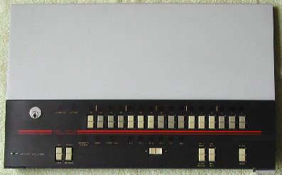
with the HP 1000 E-series front panel, the Blinkenlight board set and a 5 Volt power supply. The text markings on the E-series
is white, the background color is a shade of grayish-brown and the type indication (HP 1000 E-SERIES COMPUTER)
is yellowish-brown. The text marking on the F-series is yellowish-gold, the background is brownish and type indication
(HP 1000 F-SERIES COMPUTER) is red. I liked the colors of the E-series front panel more, so I selected that
front panel for this project. It is just a matter of taste. I will probably sell the F-series front panel.
No PC is incorporated in this setup, it is just a "front-end" that needs connection (using a 3-wire RS-232 cable) to a standard
PC running SIMH.
CONSTRUCTION
This project is a complete HP 1000 E-series 'in-a-box', which means that it has the real console.
However, this HP 1000 E-series 'in-a-box' requires an external computer (PC, Apple, SUN, SGI, any UNIX machine, etc.) that
can run SIMH. You have to compile the SIMH source code, because several modifications and additions are implemented to establish
a 2-way communication between the HP 1000E 'in-a-box' and the SIMH HP 1000 simulation.
 |
 |
| front panel of the HP 1000 F-SERIES |
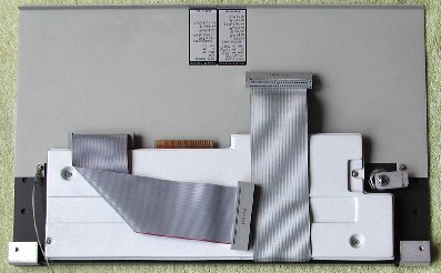
rear side of the HP 1000 F-SERIES front panel
|
As you can see, there is a large metal plate above the front panel itself. Just a small part is necessary, because the circuit board
with the electronics, LEDs and switches is a little higher than the front panel. I did not want to have a large box on my desk, so
I wanted to get rid of the excess height. My first idea was to make the height of the metal plate just as high as needed, but then
I hoped that I could cut off a part of the circuit board. I downloaded the schematic diagrams and mechanical drawings from a mirror
site of bitsavers, see
PDF file
(22 pages, 942 kb).
This PDF shows two variations of the front panel, one is by far not as high as the other. The version with the high metal front
plate adds the so-called "MPP additions". Looking at the mechanical lay-out of the circuit board and the schematic drawings, I
concluded that it must be possible to simply cut off the top part of the circuit board! I checked the traces on the circuit board
and was convinced that cutting off is indeed possible. I used a Dremel with a cutting disk to cut the circuit board just below the
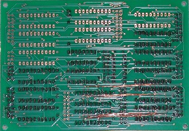
five ICs that are shown on page VIII-13/ -14. See the drawing, the blue line is where I cut the circuit board.
One important thing you can see from the drawing is that the red stripe on the ribbon cable does not mark pin #1
but pin #50!
 |
 |
|
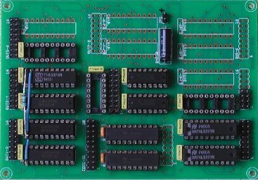
cut-off part of the Printed Circuit Board from the top of the front panel |
The white plastic cover at the rear side is mounted on the circuit board with 4 screws. The circuit board itself is mounted with
these screws and a few more onto the front panel. I removed the white plastic cover (no need for it) and removed all original
screws (#4-40 ½ inch long). Now you can remove the circuit board from the front panel, and have access to the 4 nuts that hold
the large top metal plate together with the front panel. I removed the top metal plate and replaced it with an L-shaped aluminum
profile. I had to file D-shaped openings along the side where the aluminum profile is along the circuit board side, otherwise
the aluminum profile would cover the openings for the top row of LEDs of the front panel. I will use the profile to mount the
top cover plate of the new box.
Then I put the circuit board back onto the front panel, using the original #4-40 ½ inch long screws, but for the screws that
are along the top and bottom edge I used #4-40, ¾ inch long screws. Why? I mounted two U-shaped aluminum profiles with ½
inch long standoffs isolated on the rear side of the circuit board at the top and bottom side. The Blinkenlight Core and I/O
Board are mounted on the two U-shaped profiles, thus making for a compact and complete construction of the whole thing. The
"opening" of the U-shaped profiles is towards the top and the bottom. The larger holes are drilled so you can put a screwdriver
through them to tighten the screws that mount the profiles onto the circuit board and front panel.
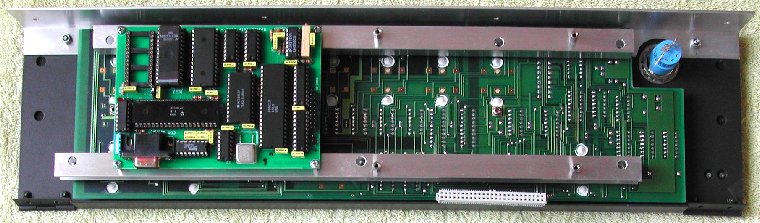 |
| Core Board mounted on U-shaped profiles |
ELECTRICAL MODIFICATIONS
The electronics of the HP 1000 front panel uses a so-called SBUS. This SBUS is a bi-directional 16-bit data path and connects
the 16 data switches, 16 data LEDs and the 6 selected register LEDs. Via this data path you can also read which register LEDs
are on.
The Blinkenlight I/O Board only has uni-directional (8-bit) input and output ports, so a small modification of the I/O Board
is needed to make two 8-bit bi-directional I/O ports from two 8-bit output ports and two 8-bit input ports. Sounds more
difficult than it really is. You just need to solder 16 wires from the outputs of two octal output latches to the inputs of
two octal input latches. I connected the outputs of output port #1 and #2 to the inputs of the input ports #7 and #8, as those
latches are close to each other on the I/O Board. Of course, when you want to read the inputs you must "disconnect" the outputs.
This is accomplished by using the "OutputEnable" pin (#1) of the output latches. Normally pin #1 of the output latches is
connected to GND on the I/O Board, thus the output are always active. I pulled the two output latch ICs from their socket
and bent pin #1 up "in the air", then reseated the ICs again. I soldered an "air wire" from both #1 pins to the output pin
of another output latch, in this case bit 7 of output port 4. Now it is possible under software control to set the data
direction of these two octal input/output latches to "READ" or "WRITE". When output
bit 7 of port 4 is "1", the outputs of the two output latches are 3-state, thus effectively disconnected from the inputs.
If you look carefully at the picture on the right you can see that I also soldered a pull-up resistor. Necessary? I do not know ...
 |
 |
| I/O Board rear side with 16 "patch" wires |
I/O Board component side with "air wire" |
I/O BOARD to HP 1000E FRONT PANEL CONNECTION
This is where most of the electrical work is ...
The HP 1000E console panel has a single 50-wire ribbon connector soldered directly onto the circuit board. The electrical diagram
in the mentioned PDF file in the "CONSTRUCTION" section shows the assignments of the pins, but I made a list. How
(which order/sequence) you connect the connector pins to the I/O Board is not particular important as you assign the output
port bits in the software. However, it is clever to allocate the Data Switches and LEDs in the proper sequence, that is, bit 0
= DATA0, bit 1 = DATA1, etc. Also, the SBUS pins (DATA0 ~ DATA15) must be connected to the created bi-directional output ports.
| 50-pin BERG connector J1 |
|---|
| 1 | PWR GND |
| 3 | DATA14 |
| 5 | DATA13 |
| 7 | POWER FAIL |
| 9 | DATA10 |
| 11 | DATA9 |
| 13 | PWR GND |
| 15 | RUN |
| 17 | IBL |
| 19 | INC M |
| 21 | RIGHT |
| 23 | STORE |
| 25 | STROBE |
| 27 | DIEN |
| 29 | EXTEND |
| 31 | HLTB |
| 33 | DSPEN |
| 35 | DSPCL |
| 37 | PPS |
| 39 | DATA7 |
| 41 | PWR +5V |
| 43 | DATA4 |
| 45 | DATA3 |
| 47 | PWR +5V |
| 49 | DATA0 |
|
| 2 | DATA15 |
| 4 | PWR +5V |
| 6 | DATA12 |
| 8 | DATA11 |
| 10 | PWR +5V |
| 12 | DATA8 |
| 14 | RUNB |
| 16 | PRSTB |
| 18 | INSTEP |
| 20 | DEC M |
| 22 | LEFT |
| 24 | DISPLAY |
| 26 | DIST |
| 28 | OVERFLOW |
| 30 | PWR GND |
| 32 | PARITY |
| 34 | DSPST |
| 36 | PWR GND |
| 38 | PWR GND |
| 40 | DATA6 |
| 42 | DATA5 |
| 44 | INTL |
| 46 | DATA2 |
| 48 | DATA1 |
| 50 | PWR GND |
|
|
I used the following color scheme in the table.
- red - connections to LEDs
- green - connections toggle switches
- blue - bi-directional connections (LEDs / switches)
- black - power supply connection. +5 Volt or GND.
The ribbon cable had a PCB edge connector at the other end, which I had cut off. I used female header counterparts to plug into
the header pins on the I/O Board. When I finished that job, I double checked before applying power. AARRGGHHH !! The red
stripe on the ribbon cable did not identify where pin #1 was, but where pin #50 was.
Who at HP came up with that stupid idea?!
I had to cut the female header counterparts, and of course the wires which were cut to appropriate length are now either too
long (not a problem) or too short ... So I went for a drastic change. I cut off the ribbon cable close to the circuit board and
put an IDC female header connector on the ribbon cable. Using two simple male header pin strips of 25 pins I soldered colored
wires (from a ribbon cable) to the female header counterparts.
Using colored wires makes a visual inspection easy. After assuring everything was wired correctly it was time to apply power.
Yes! Some LEDs light lit up, and the DATA LEDs were all off as expected, because of the power-up reset
circuit. The DATA LEDs can be switched on and off by pressing the data switches, and pressing the
CLEAR DISPLAY switches all DATA LEDs off.
|
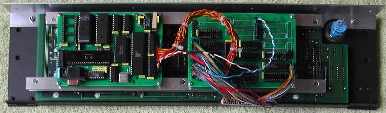 |
| Core Board and I/O Board wired to the front panel |
FIRMWARE MODIFICATIONS
Time to write some firmware.
As the I/O Board is modified to support two 8-bit bi-directional data port, the Blinkenlight software V1.5 has to be changed.
This is a "one-of-a-kind" project, so I wrote firmware just for this HP 1000E front panel. It is of course also usable
for the other HP 1000F front panel (if I decide to sell that one). I implemented a simple stand-alone functionality and of course
interface routines to communicate with SIMH. In stand-alone mode the DATA switches are already
functional; when you press the upper part the corresponding DATA LED is turned ON,
when you press the lower part the corresponding DATA LED is turned OFF. With the
CLEAR DISPLAY switch you can turn OFF all DATA LEDs.
I decided that in stand-alone mode the RUN LED must be turned OFF, and to have
some LEDs active, the POWER FAIL LED is turned ON. To give the front panel some
"life", I implemented a running light on the REGISTER LEDs: A/x ,
B/y , M/m , T/t ,
P/f , and S/s. While the firmware is in Stand-alone Mode, it only listens
to the "start HP 1000E Console Mode" command, the ASCII letter 's'.
In HP 1000E Console Mode the following one-letter commands are implemented.
| command | additional data | description |
|---|
| D | 2 bytes | output to DATA LEDs, 1st byte=D15~D8, 2nd byte=D7~D0 |
| R | 1 byte | output to REGISTER LEDs |
| S | 1 byte | output to STATUS LEDs |
| Q | --- | query the switches once, receive 5 bytes |
| q | --- | query the switches every second, abort by ESC |
| T | --- | clear all toggle "message sent" flags |
| t | 2 bytes | clear specific toggle "message sent" flags |
| c | --- | (re)start HP 1000E Console Mode |
| p | 2 bytes | test output port, 1st byte=port#, 2nd byte=data |
| s | --- | start Stand-alone Mode |
The commands 'q' and 'p' are implemented for debugging purposes. They are not designed to be used by SIMH.
I have not yet started on the modifications in SIMH to make SIMH communicate with the HP 1000E / Blinkenlight setup. It might
turn out that the DATA and the STATUS LEDs (for example) are often updated at the same
time. In that case I will add a few more commands, probably taking the letters 'X', 'Y', and 'Z'. If the DATA
and STATUS LEDs need update at the same time, the separate commands would take 5 bytes communication, whereas
the 'X' command (for DATA and STATUS) would need 4 bytes ... less overhead.
The implemented commands assume a specific wiring of the input and output ports from the I/O Board to the HP 1000E console.
| bit | OUT #1 | OUT #2 | OUT #3 | OUT #4 | IN #1 | IN #2 | IN #7 | IN #8 |
|---|
| 0 | SB0 | SB8 | INTL | PPS | IBL | HLTB | SB0 | SB8 |
| 1 | SB1 | SB9 | PARFF | DSPCL | INC M | RUNB | SB1 | SB9 |
| 2 | SB2 | SB10 | EXFF | DSPST | RIGHT | PRSTB | SB2 | SB10 |
| 3 | SB3 | SB11 | OVERFF | DSPEN | STORE | - | SB3 | SB11 |
| 4 | SB4 | SB12 | RUNFF | DIEN | INSTEP | - | SB4 | SB12 |
| 5 | SB5 | SB13 | PF | DIST | DEC M | - | SB5 | SB13 |
| 6 | SB6 | SB14 | - | - | LEFT | - | SB6 | SB14 |
| 7 | SB7 | SB15 | - | IOCTRL | DISPLAY | STROBE | SB7 | SB15 |
» INPUT port #7 is wired to OUTPUT port #1 and INPUT port #8 is wired to OUTPUT port #2 on the I/O Board.
» OUTPUT port #4 bit 7 controls the 3-state OE* of OUTPUT port #1 and OUTPUT port #2.
BOX FOR THE HP 1000E CONSOLE
The bottom side of the metal plate of the HP 1000E front panel is not at a 90° angle, but slightly bent "inwards". That means
that if the front panel is resting on that edge of approximately ½ inch, the panel stands at a nice usable angle. If the
panel would be at an 90° angle on the desk, the operation of the switches is not so comfortable. So I decided to use that edge
to give the panel a nice view angle and "ergonomic" access to the switches.
I used Front Panel Express, which you can download and use freely.
Side panels
The left and right side panels of the box also have that angle at the front side and have a cavity of 7 mm on the inner side so
that the sides of the HP 1000E front panel can be placed in those cavities.
On the inner side of each side panel are three L-shaped profiles attached:
- to mount the sides panels on the bottom plate
- to mount the top cover
- to push the HP 1000E front panel against the front-sided edge of the cavity.
All profiles are mounted with short screws in blind threaded holes on the inside, so none of these screws are visible
on the outside of the box.
Bottom and top cover
With this construction the HP 1000E is firmly mounted to the sides of the box, and the sides of the box are attached to the
bottom and top cover. A few aluminum strips are attached to the bottom plate to clamp the bent edge of the HP 1000E front panel
against the bottom. Strictly, this is not necessary, but it will add to the strength of the box.
Note that the bottom and top cover plate are a little longer than the front panel, because approximately 3 mm of the front panel
is "hidden" in the cavity of the side panel. This approach 'masks' the tolerance of the length of the bottom and top cover
compared to the length of th HP 1000E front panel.
Rear cover
On the rear cover are the things you would normally find. Besides the mains connector (with integrated switch and fuse) there
is of course the 9-pin female D-SUB connector for the RS-232 connection to the PC, and two push-buttons for the Core Board.
One push-button to reset the 6809 CPU and the other push-button enables start-up of the Core Board in "monitor mode".
A few ventilation slits are added for free air flow.
Power supply
A standard power supply is installed on the bottom plate of the box. Initially I wanted to install a standard PC ATX power
supply, because that power supply supports switching (completely) on by connecting a wire to GND. However, I was so lucky to
find a key switch that can switch the mains power supply, so I replaced the mechanical key front panel lock with an electrical
key switch. I no longer needed an ATX power supply, and since the whole setup only needs +5 Volt, I searched and found a small
tall 5V power supply. With this power supply the box does not need to be as deep as it would have to be when an ATX power supply
was installed. The ATX power supply is at least 8 cm deep, unless you find a mini-ATX power supply, but those are a bit
difficult to find and often cost more money.
More to follow ...