| PDP-11/10 PROCESSOR RESTAURATION PROJECT | 11/10 |
This PDP-11/10 was used in a company called "Software Sciences", before the company was taken over by IBM. The company was called "Data Sciences" later on. What makes this PDP-11/10 special is the fact that Hans (and others) developed the software for the air traffic control system of Ballygirreen (in Ireland, on the most western location of Europe) on this machine. Cool.
This page will describe my steps and efforts to get this PDP-11/10 operational again. Parts may be useful on other machines.
| ||||||||||||||||||||||||||||||||||||||||
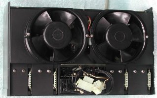
 I decided to clean the power supply before testing it. Seven screws hold the top rear cover plate and each fan is mounted on the
front of the PSU chassis with two long screws. After you removed the top rear cover plate you can remove the power bricks. They are
installed in the PSU with two big screws on the top, and a smaller screw at the rear side. After you remove these three screws you
can slide the power brick out of the PSU chassis. I did not remove the transformer. After this disassembly you can clean the box.
I decided to clean the power supply before testing it. Seven screws hold the top rear cover plate and each fan is mounted on the
front of the PSU chassis with two long screws. After you removed the top rear cover plate you can remove the power bricks. They are
installed in the PSU with two big screws on the top, and a smaller screw at the rear side. After you remove these three screws you
can slide the power brick out of the PSU chassis. I did not remove the transformer. After this disassembly you can clean the box.
As it is not clear from where the smoke came, I hope it was the PSU ... You have two options to test them.
Either separately on the bench, or in the H765 chassis. If you go for the second method, you need the rest of the BA11-K box,
because the wiring from the transformer to the power modules goes through the power distribution board which is installed in the
box. As that is a "heavy" setup to test the power modules, and access to them is difficult under test, the first method is a lot
easier. All you need is a 20 to 30 VAC power source. A small transformer 24VAC/1A. will do fine. However, the H745 also needs +15V
input for the regulator in that power brick.
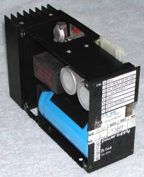
A label on the power brick clearly shows how you must connect them, click on the power brick. Pin #1 is closest to the front where
the label is.
Jump in time ... some 6 years!
My computer collection has found its final home. I now have a "hangar" (a former pig stable) with some 2200 square ft surface
(approximately 200 square meters). In August 2015 I could pick up two H960 racks in Amsterdam. They were empty and quite dirty,
but with the two racks came also two side panels, and both racks had the rear door and "utility" frame. It took 3 hours to clean
up one rack, and it now looks great. Amazing how these racks stay in great shape after many, many years. These two racks are
probably older than the others that I have. All my racks use rivets, but these two are welded!
Anyway, finally this sick PDP-11/10 will get a "house" of its own. Till now, the PDP-11/10 was a "visitor", living above the
PDP-11/34C.
In the PDP-11/10 rack is also mounted the TU60 cassette tape drive and an RX01 dual 8" floppy disk drive. In the
bottom at the rear side is the 861 Power Controller (aka "switch box"), and above the 861 is a battery backup unit. I will not
use the battery backup unit, but it is heavy, just what I need as a counter-weight when the PDP-11/10 is outside the rack on
its slides. You sure do not want the rack to tilt towards you when the CPU box is pulled out!
Now that the PDP-11/10 hangs on its slides in the rack, it is easy to work on it. First, I made notes of the location of all the
boards in the BA11-K box, then I pulled all the boards starting at the "end" of the UNIBUS and stored them in ESD-safe bags. The
last board pulled first makes the pulled CU boards (M7261 and M7260) on top of the stack. You will need those first eventually.
Then I cleaned the box, but as I did that some 6 years ago, there was not much to clean out. I pulled the box on its slides out
of the rack swung it 90 degrees upward and removed the bottom cover to get access to the power distribution panel.
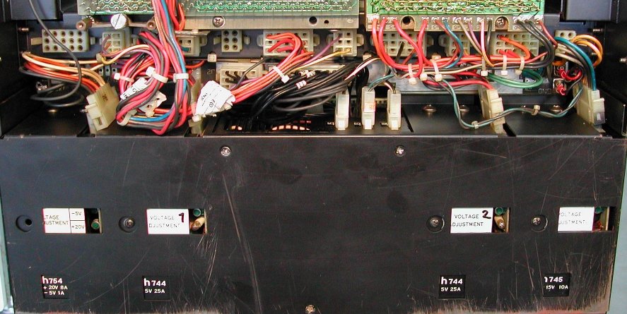
The picture shows the 4 power bricks. The two H744 and the rightmost H745 are already connected to the distribution panel, the
leftmost H754 is not yet connected. The fans start to rotate when I turn the key switch on the operator panel. With the Fluke
Volt meter I checked the voltages on the CPU backplane, the rightmost backplane in the picture. The "+5" connection (red wire)
measures 5.11V, the +15" (grey wire) measures +16.18V, and the "-15" (blue wire) measures -15.06V. The second H744 supplies
power to the second backplane and measures +5.04V. These voltages are all within specifications, so the power supplies seem to
be OK. I had prefered smoke from the power supply, because that would probably be easier to repair. But the power supply seems
to be fine. Finally, I connected the H754 power brick, and again on the CPU backplane, I checked the "+20" and "-5" connections.
"+20" (orange wire) measures 20.22V and "-5" (brown wire) measures -5.07V. Again, good voltage levels. Next to the small voltage
trim potentiometer is a lamp. It should be on when there is output power, but most of the time this bulb is defective. Of the
4 power brick, only H744 #1 had a lamp that lit when power was on.
The AC LO connection (yellow wire), DC LO connection (purple wire) and LTC connection
(brown wire) also look good with the Volt meter. AC LO and DC LO measures 4.92V, and
LTC measures 2.49V. The LTC voltage also looks fine, as it is a square wave, 50 Hz, duty cycle 50%. However, the
AC LO and DC LO signals should also be inspected with an oscilloscope. The voltage
levels must be clean, without "spikes". If the voltage level is not clean, the PDP-11 can behave very erratically. The scope
shows that on both AC LO and DC LO have a ripple of 130 mV. That seems OK to me.
Console maintenance
I downloaded
DEC-11-H05AA-A-D_1105um.pdf from "bitsavers". In the last chapter some tests are described
that you can do.
I hope to find the problem by elimination. Chapter 6.11 describes a few useful checks to verify the console stand alone. Great!
All 8 tests check out just fine, but ... the data pattern on the LEDs is "inverted"! The manual says for test numbers 5, 6, 7, and
8 that the LED pattern must be 052525, 031463, 007417,
and 0003777 respectively. I got exactly the opposite data: 125252,
146314, 170360, and 177400! Very weird.
Next, I downloaded
EK-KD11B-MM-001_Jan75.pdf as a preparation to some microstepping/debugging of the CPU. To my surprise,
in the back is a chapter 5.11 "Console maintenance". It describes exactly the same tests, but now the LED data is different ... it
is what I am seeing! So, I am happy to say that the console is eliminated as a problem source.
A lot more to come ...!
| Back to top of this page |