PDP-11/20 OPERATOR'S CONSOLE
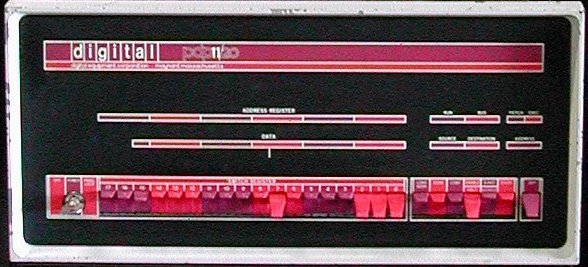
The manual operation of the PDP-11/20 is controlled by switches on the KY11-A programmer's console. Visual displays
indicate processor operation and the contents of address and data registers. All register displays and switches are
numbered from right to left, the most significant bit is at the left. Note that the PDP8 numbered from left to right,
although the most significant bit was also at the left side.
- Console indicators
- DATA
-
Displays the information within the data paths of the processor.
When the console switches are used, information shown on the DATA display is as follows:
- LOAD ADDRS : no indication
- DEP : the Switch Register information just deposited.
- EXAM : the information from the address examined.
- S-INST : when stepping through a program a single instruction at a time, there is no indication on the DATA display.
- S-CYCLE : the information last in the data paths (refer to flow diagram). Usually is a derivative of last bus data.
During HALT and WAIT instructions, information shown on the DATA display is as follows:
- WAIT : the RUN light is on, no indication on the DATA display.
- HALT : when bus control is transferred to to the console on a HALT instruction, processor register R0 is displayed.
During DMA operations, the processor is not involved in data transfer functions. Therefore, the data displayed in the
DATA display is not that of the last bus operation.
- ADDRESS REGISTER
-
The ADDRESS REGISTER is an 18-bit display and shows the address in the Bus Address Register (BAR) of the processor.
This is the address last used by the processor on the bus. The two most significant digits (A17, A16) are ordered
according to the lower 16 bits; A17 and A16 are set only when bits A15, A14 and A13 are set. Addresses between
160000 and 177777, therefore, are translated to addresses between 760000 and 777777, respectively.
When the console switches are used, information shown on the ADDRESS REGISTER display is as follows:
- LOAD ADDRS : the transferred Switch Register information
- DEP or EXAM : indicates the bus address just deposited into or examined.
- S-INST or S-CYCLE : indicates the last processor bus address.
During a programmed HALT or WAIT instruction, the ADDRESS REGISTER displays the address of the instruction. The
Program Counter (PC) is the BAR value plus 2.
During DMA operations, the processor is not involved in data transfer functions and the address displayed in the
ADDRESS REGISTER is not that of the last bus operation.
- RUN
-
When the RUN indicator is on, the processor clock is running. The processor has control of the bus and is operating on
an instruction. When the RUN indicator is off, the processor is waiting for an asynchronous peripheral data response,
or the processor has given up bus control to the console or to a peripheral.
During normal machine operation the RUN light will flicker on and off (indiacted by a faint glow).
Special situations exist for programmed HALT and WAIT instructions:
- WAIT: the RUN light is completely on
- HALT: the RUN light is completely off
During machine operation, with S-INST or S-CYCLE control transferred to the console, the RUN light is off.
- BUS
-
When the BUS indicator is on, a peripheral device (other than the console) is controlling the bus.
When both BUS and RUN indicators are off, the bus control has been transferred to the console.
The BUS light is probably never seen except when there is a bus malfunction or when a peripheral holds the bus for
excessive periods of time.
During machine operation, with S-INST or S-CYCLE, control is transferred to the console and the BUS indicator is off.
- FETCH
-
When on, the processor is in the FETCH major state and is obtaining an instruction.
During the FETCH major state, only FETCH and RUN indicators are on if no NPR's are honored.
- EXEC
-
When on, the processor is in the EXEC major state. The processor performs the action specified by the instruction.
(HALT, WAIT and trap instructions are executed in Service).
During the Execute major state, only EXEC and RUN indicators are on if no NPR's are honored.
- SOURCE
-
When on, the processor is in the SOURCE major state and is obtaining source operand data. The processor calculates
source address data as indicated by cycles of the ADDRESS lights.
During the SOURCE major state, SOURCE and RUN indicators are both on; ADDRESS lights may be on in various combinations.
The BUS indicator is off if no NPR's are honored.
- DESTINATION
-
When on, the processor is in the DESTINATION major state and is obtaining destination operand data. The processor calculates
destination address data as indicated by cycles of the ADDRESS lights.
During the DESTINATION major state, DESTINATION and RUN indicators are both on; ADDRESS lights may be on in various
combinations.
The BUS indicator is off if no NPR's are honored.
- ADDRESS
-
Two lights representing a 2-bit binary code. When lit, indicate bus cycles used to obtain address data during Source and
Destination major states. The 2-bit binary code indicates which address cycle (1, 2, or 3) the machine is in during the
Source and Destination major state. Whenever either one or both ADDRESS lights are lit, either SOURCE or
DESTINATION indicator is on.
The BUS indicator is off if no NPR's are honored.
-
Notes.
- When the processor is in a major machine state (FETCH, EXEC, SOURCE, DESTINATION), the appropriate major state indicator
is on and the following, associated RUN and BUS conditions occur.
- The RUN indicator is on when the processor clock is running (processor in control of bus).
- The RUN indicator is off when the processor is waiting for data from the bus (processor in control of bus, but clock is off).
- The RUN indicator is off and the BUS indicator is on when an NPR is being serviced (processor in not control of bus).
- There is no major state indicator on the console for the major machine state of Service. In this state, break requests are
honored, machine instructions of WAIT and HALT are executed, and trap sequences for instruction and bus interrupts are implemented.
- Console controls
- OFF/POWER/PANEL LOCK
-
This is a 3-position key-operated switch.
Provides power control to console and lock-out of console controls as follows:
- OFF position
Removes all power from the processor.
- POWER position
Applies primary power to the processor. All console controls are fully operational when the switch is in this position.
This is the normal operation position.
- PANEL LOCK position
Disables all console (panel) controls except the SWITCH REGISTER key switches. This prevents inadvertant switch operations
from distubing a running program. The processor is operating, but the console is disabled.
The data entered in the SWITCH REGISTER are still available to the processor whenever the program explicitly addresses the
SWITCH REGISTER (address 777570).
- SWITCH REGISTER
-
The 18 key-type switches provide a means of manually loading a 16-bit address or 16-bit data word into the processor.
The up position is a logical one (or on). The down position is a logical zero (or off). The processor ignores bit 17 and 16;
these switches may be set to either position. For addresses using bit 17 and 16, these bits are set within the processor if
bits 15, 14 and 13 are set.
If the word in the SWITCH REGISTER represents an address, it can be loaded into the ADDRESS REGISTER by depressing the
LOAD ADDRR key.
If the word contains data, it is loaded into the address specified by the ADDRESS REGISTER by lifting the DEP key. The data
appear in the DATA display.
The contents of the SWITCH REGISTER may be used by the processor any time the program explicitly addresses the register at
address 777570. This address can only be used by the processor.
- LOAD ADDR
-
The LOAD ADDR switch is a momentary key-type switch which must be depressed to activate and transfers the SWITCH REGISTER contents
to the Bus Address Register (BAR) through a temporary location (TEMP) within the processor. This bus address, displayed in
the ADDRESS REGISTER, provides an address for the console functions of EXAM, DEP, and START.
Odd bus address (bit 00 enabled) should not be entered from the console. Upper bytes at these odd addresses can be examined
or deposited by using the word address (bit 00 not enabled).
- EXAM
-
The EXAM switch is a momentary key-type switch which must be depressed to activate and transfers the contents of the bus address
(which is specified by the Bus Address Register) for DATA display. After use, the data appear on the DATA display and the address
of the data is in the ADDRESS REGISTER. A LOAD ADDR operation pre-establishes the initial address; sequential addresses occur
automatically. If the EXAM switch is depressed twice in succession, the contents of the next sequential bus address are displayed
in DATA. This action is repeated each time EXAM is depressed provided no other switch is used between these steps.
Whenever LOAD ADDR or DEP switch is used, it destroys the incrementing sequence. The next time EXAM is used,
it displays the current Bus Address Register address rather than the next sequential address.
- CONT
-
The CONT switch is a momentary key-type switch which must be depressed to activate and causes the processor to continue operation
from the previous point at which it had stopped. I a program stops, depressing CONT provides a restart without power clear.
If the HALT/ENABLE switch is set in the ENABLE mode, CONT returns bus control from the console to the processor
and continues program operation. If the HALT/ENABLE switch is set to HALT, depressing the CONTkey causes the
processor to perform either a single instruction or a single bus cycle (dependent on the position of the S-INST/S-CYCLE switch) and then stops.
Bus control has been returned to the console and the CONT switch must be used to continue.
- ENABLE/HALT
-
This 2-position key-type switches allows either the program or the console to control processor operation.
- ENABLE position
permits the system to run in a normal manner. No console control requests (type dependent upon S-INST/S-CYCLE switch) are made.
Without console control, all switches except ENABLE/HALT and SWITCH REGISTER are disabled. Continuous program control requires the ENABLE mode.
- HALT position
halts the processor and passes control to the console; with the S-INST/S-CYCLE switch in the S-CYCLE mode, console switches
(except SWITCH REGISTER, CONT, and ENABLE/HALT) are disabled unless the machine is stepped to the end of an instruction.
In the S-INST mode, the processor stops at the end of an instruction and all console switches are enabled.
The Halt mode is used with the CONT switch to step the machine through programs and facilitate intermediate observations. The
HALT mode is used to interrupt program control, perform single step operation, or clear the system.
When the START switch is activated in the HALT mode, a system clear is effected.
- S-INST/S-CYCLE
-
2-position, key-type switch. Allows the processor to step through program operation either one instruction or one bus cycle at a time.
The user may note processor operation and contents of registers during major states or bus cycles of individual instructions. This
switch is enabled by the ENABLE/HALT switch in the HALT mode.
- S-INST position
The processor halts after an instruction. This process is repeated each time the CONT switch is depressed. Console switches (LOAD ADDR,
EXAM, DEP) can be used when the processor halts. Control is transferred to the console by a console bus request (CBR), second
highest priority and serviced at instruction end.
- S-CYCLE position
The processor halts after a bus cycle. The process is repeated each time the CONT switch is depressed. Console switches are
inoperative unless the machine is stepped to the S-INST halt position. (Changing mode to S-INST and using CONT switch
effects this). Control is transferred to the console by a console nonprocessor request (CNPR), highest priority and serviced after a bus cycle.
- START
-
The START switch is a momentary key-type switch which must be depressed to activate. When ENABLE/HALT is set to ENABLE,
depressing START provides a system clear operation and then begins processor operation. A LOAD ADDR operation pre-establishes the starting
address.
When ENABLE/HALT is set to HALT, depressing START provides a system clear (initialize) only. The processor does not start;
the Bus Address Register is loaded from a temporary processor register (TEMP) which is usually pre-loaded by LOAD ADDR. This provides the only
method of reading TEMP when it does not contain the LOAD ADDR value.
- DEP
-
The DEP switch is a momentary key-type switch which must be lifted to activate. The DEP switch transfers the contents of the console
SWITCH REGISTER to the bus address (specified by Bus Adddress Register). After use, the data appear on the DATA display and the address
is in the ADDRESS REGISTER. A LOAD ADDR operation pre-establishes the initial address; sequential addresses occur automatically.
If the DEP switch is raised twice in succession, the contents of the SWITCH REGISTER is deposited in the next sequential bus address
location. The action is repeated each time DEP is raised provided no other switch is used between these steps. Whenever the LOAD ADDR
or EXAM switch is depressed, the incrementing sequence is destroyed. The next time DEP is used, it deposits the current address rather
than the next sequential address.