Jumps within this page are:
|
|
| PDP-11/34A PROCESSOR OVERVIEW | 11/34A |
The PDP-11/34A (KD11-EA) is an upgraded version of the PDP-11/34 (KD11-E) processor.
The basic components of the PDP-11/34A processor are a system unit, which is a dedicated 9 slot backplane (DD11-PK), and the
following two boards:
Jumps within this page are:
|
|
|
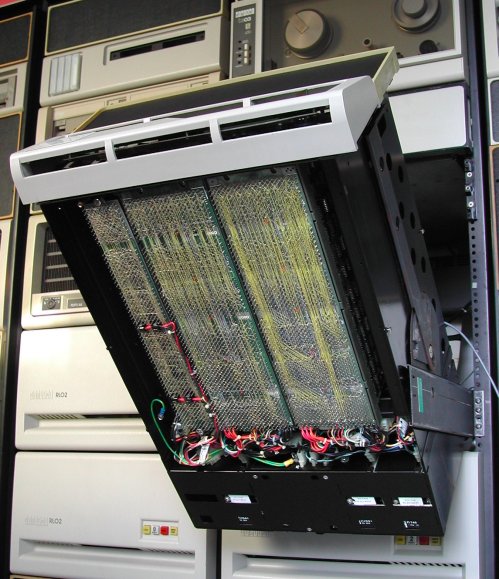
The KD11-E backplane is a dedicated backplane wire-wrapped to connect the 11/34(A) CPU boards. This means that each board has a specific slot allocated and the board must be installed at the correct position.
The data paths (M8265) and control paths (M8266) modules are connected via the processor backplane (DD11-PK).
The location of the M7859, M9312,M8267, and the M8268 depend on which of these are actually installed. The slot numbers in the table are correct if these boards are all installed. This is the maximum 11/34A processor configuration. For more detailed information see in the options folder the documents "FIS", "cache", and "bootstrap". |
|
||||||||||||||||||||||||||||||||||||||||
Slot 9, positions A and B carry the signals of the UNIBUS. At this location is either a UNIBUS termination module
(which is an M9302 for the PDP-11/34A), or a module for interconnection to the next system unit. The interconnection
is done with a module bridge, M9202.
Slot 9, positions C thru F, is a so-called SPC slot. SPC stands for Small Peripheral Controller. The common use of
this SPC slot is the interface module to connect the system console. I have an M7856 installed in this slot, which
provides one single RS-232A asynchronous connection for the system console. With a switch box the asynchronous comm line
is connected to the VT102 console at 9600 Bd. I use a switchbox because the VT102 can thus also be connected to the
PDP-11/44.
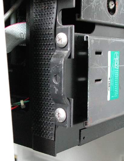
The console is installed on the BA11 box with two simple brackets. In the picture you see the righthand side. The bracket is installed on the BA11 box with two screws. Just one screw in the middle of the bracket holds the console panel in its place.
The grey round cable in the top of the picture connectes to the M9312 Bootstrap/Terminator module with FAST-ON TABs and is wired to the rotary knob on the front panel via the circuit board attached to the rear ised of the front panel.
The ribbon cable connects to the M7859 KY11-LB Programmer's Console Interface with an IDC connector. The cable carries multiplexed signals to scan and read the keypad and control the six 7-segment displays, and the three LEDs.
I think the twisted red/green/black cable are the power supply wires to the console, but I can not
remember that detail. I am too lazy to remove the console panel and have a peek ...
For the basic 11/34 processor the following diagnostics are available.
| «-» | FKAA(x) | 11/34 CPU test |
| «-» | FKAB(x) | 11/34 TRAP test |
| «-» | FKAC(x) | 11/34 EIS test |
| «-» | FKTG(x) | 11/34 instruction I/O exerciser |
| «-» | FKTH(x) | 11/34 memory management |
| «-» | FFPA(x) | 11/34 FP11-A part 1 |
| «-» | FFPB(x) | 11/34 FP11-A part 2 |
| «-» | FFPC(x) | 11/34 FP11-A part 3 |
| «-» | FKKA(x) | 11/34 Cache test |
| Return to TOP of this page | Return to HOME page |