 This page shows my PDP-11/45 system. It is sort-of a restauration project as the system has been in dry storage for many years.
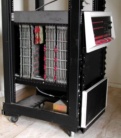
In that storage room were two PDP-11/45's, each in a H960 cabinet. One 11/45 consists only of the front panel and
an empty BA11-FA mounting box, while the other 11/45 has all processor modules twice inserted in the backplane, and in the first
slots (where the hardware floating point modules go) are other board plugged. This mounting box was used as "module storage" for both
systems.
The picture shows the machine as it was in storage, so do not make any references to the inserted modules as you can see them! Not visible
on this pictures are the two H7420 power supply units, which are installed on the vertical posts of the rack, behind the mounting box.
The PDP-11/45 was the most powerful PDP-11 to date and was introduced in 1971.
The PDP-11/45 was an excellent computational tool for large multi-user, multi-task installations. Through memory management, memory could
be expanded to 128K, which included a combination of bipolar and MOS memory. Other features included a greatly expanded floating point
processor.
In many aspects, the PDP-11/45 looks similar to the PDP-11/70 which was introduced in February 1975.
The PDP-11/70 added, among others, a larger memory space (up to 4M) and cache memory.
GENERAL SYSTEM INFORMATION
- System history
-
This PDP-11/45 has been in use at the LTCC, "London Terminal Control Center", in the United Kingdom. The PDP-11/45's were originally
part of the PRDS (Processed Radar Display System), which was built by Plessey, and they were in service from around 1980 until 2005.
During its 25 year operational life, it never suffered a major failure!! Ask any PC owner how his machine ran the last couple
of years ...
The PRDS system was built mainly from PDP-11/34's, and two 11/45's, and provided a composite map of UK airspace, based on 16 mile x 16 mile
grid squares, with a main and alternate radar source for each square. This allowed a controller to use a trackball to move around UK
airspace, and meant that there were no jumps or glitches when following an aircraft. The Radar input was connected to one set of 11/34's
and the displays driven by another set (one 11/34 for each display). There were around 150 (!) PDP-11/34's in the system. The 11/34's were
all booted remotely from the PDP-11/45's, and the system ran under RSX-11. The PDP-11/45's also interfaced with the central flight
processing computer system (originally an IBM 9020).
- System description
-
The PDP-11/45 consists of the basic KB11-A 11/45 Central Processing Unit, and can have the several processor options. The processor boards
and the options are all described on the page CPU information, a subfolder of the PDP-11/45 folder. The
PDP-11/45 processor and options are :
- KB11-A PDP-11/45 and PDP-11/50 basic processor
- KB11-D PDP-11/55 basic processor
- KT11-C Memory Management Unit
- KT11-CD Memory Management Unit
- MS11-BC MOS Memory Control
- MS11-BP 4K MOS Memory
- MS11-CC Bipolar memory Control
- MS11-AP 4K Bipolar Memory
- FP11-B Floating Point Processor
- FP11-C Floating Point Processor
- MR11-DB Bootstrap Loader
- KW11-L Line Time Clock
-
The basic PDP-11/45 and 11/50 systems, prior to 1976, were available with a KB11-A central processor, an FP11-B floating point unit, and
MOS or bipolar memory. With the introduction of a high-performance floating point unit (FP11-C), the KB11-A underwent extensive revision,
generating a new CPU version, the KB11-D. An entirely new system, including the KB11-D, FP11-C and bipolar memory is called the PDP-11/55.
The PDP-11/45 and 11/50 systems are still as they were prior to 1976, but the PDP-11/45 is also available with the KB11-D and its
compatible options.
- The basic PDP-11/45 uses a KB11-A or KB11-D central processor and can have either (or both) MOS and bipolar memory.
- The basic PDP-11/50 uses a KB11-A central processor and solid-state (MOS) memory.
- The basic PDP-11/55 uses a KB11-D central processor and bipolar memory.
Each basic system generally contains a minimum of 16K words of memory.
11/45 SYSTEM CONSOLE
The front panel of the PDP-11/45 ... more to come ...!