A year ago I found a PDP-11/60 in the corporate cabinet, but I did not have the means to transport it to my house. The only thing
that I took was the console, to prevent cosmetic damage to it. I decided that I would take the system during the visit the next
time (May, 2005).
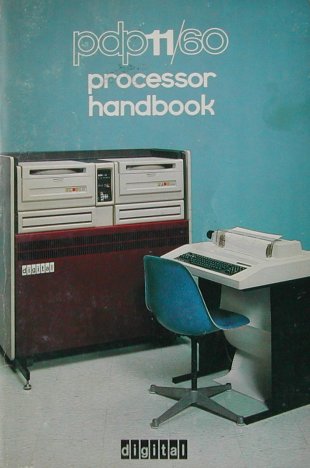
However, due to available room restrictions, I was sure that I could never put the complete corporate cabinet, as shown on the
cover of the processor handbook, at my place. So I decided to go for the CPU box and its power supply, the wiring harnesses, the
power controller and all loose bits in the cabinet. I already had the console and the console static protection/connection board,
and planned to build the PDP-11/60 in a tall H960 cabinet.
DIGITAL introduced the PDP-11/60 in March 1977.
The PDP-11/60 has some attributes that makes the machine interesting. The 11/60 has an option called WCS (Writable Control Store)
that allows a user to write his own micro-code and let the processor execute the new instruction(s) at full speed! There
are 3 different WCS options:
- M7870 = WCS - Writable Control Store (KU-116)
- M7871 = DCS - Diagnostic Control Store
- M7871-YA = ECS - Extended Control Store
The only other PDP-11 that has a WCS option (KUV11, M8018) is the PDP-11/03, KD11-F processor.
Ritchie Lary wrote the micro-code for the PDP-11/60 to emulate the PDP-8 instruction set, making it the "fastest PDP-8 ever".
It is a pity that the source code seems to be lost. Even Ritchie Lary, the author, no longer had the source when Eric Smith
inquired some years back (~2011 - 2012), and Ritchie did not think that anyone else was likely to have it. So, it appears to be
lost forever.
Update from Paul Koning (Feb. 2018)
A few more snippets of information: it was used by the WPS-8 development group in Merrimack, NH (a few cubes over from my first office
at DEC). The host ran RSTS/E, and there was a RSTS "Runtime System" as part of the machinery.
I've never seen any of the code; the brief description above is all I know.
Jumps within this page are the following.
GENERAL SYSTEM INFORMATION
 The PDP-11/60 is a somewhat rare machine, as it was not one of the more popular models. Arguably, the processor should have been
designed with the PDP-11/45-55-70 style 22-bit memory management, not the PDP-11/40-34 style (18-bit).
The PDP-11/60 is a somewhat rare machine, as it was not one of the more popular models. Arguably, the processor should have been
designed with the PDP-11/45-55-70 style 22-bit memory management, not the PDP-11/40-34 style (18-bit).
Perhaps the non-popularity of the PDP-11/60 caused the machine to have a short life span during which it was shipped (only from
1977 to 1981 or so).
However, the Floating Point (option FP11-E) is pretty good, and of course the PDP-11/60 was user micro-programmable.
The system was available in 4 different configurations. Three configurations were housed in a Low Boy Corporate cabinet.
The main difference between these three was the installed mass storage option in the top left and right side. The choice available
was either two RK06 removable pack disk drives, or a combination of a RK05f fixed and RK05j removable pack disk drive, or no mass
storage peripherals at all, just two blank panels. The fourth configuration is housed in a High Boy Corporate cabinet and does not
have any peripherals in the cabinet.
Here you see my Low Boy cabinet system in its original state. The expansion card cage is already outside the cabinet.
The two upper bays contained a PC05 paper tape reader/punch at the left side and an RX01 floppy drive unit at the right side.
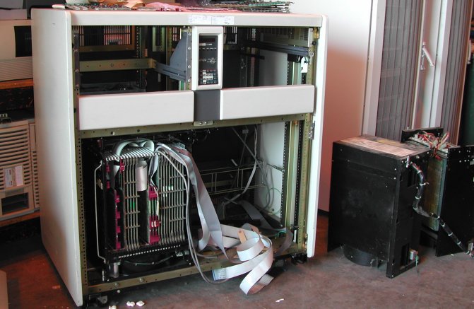 The PDP-11/60 console is installed in the middle between the left and right side at the front.
The card cage with the 11/60 processor is in all four configurations installed in the lower left (front) side of the cabinet. The
lower right (front) side is available for the expansion card cage. The power supplies (one for each card cage), the power
controller, and for MOS memory optional Battery Back-Up power supply are installed at the rear side of the cabinet.
If the FP11-E Floating Point option is installed (4 additional boards in the CPU backplane), an additional separate power supply
is mounted in the rear side of the cabinet.
more to be added ...
back to top
11/60 SYSTEM CONSOLE
The system console is in the middle at the front side of the corporate cabinet between the two bays, but my H960 rack-mount
(home-brew) version the console is installed on a blank panel. See the page "11/60 in H960 rack".
If you have other ideas for the installation of the system console in an H960 rack configuration, let me know!
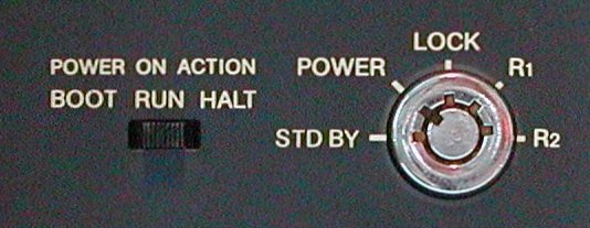
The 11/60 console (KY11-P) resembles the PDP-11/34A "full" console: it has the calculator-style keypad and the six 7-segment
red LED displays. A key switch is used to turn on/off and control the system.
| PDP-11/60 programmer's console switches |
|---|
 |
5-position
key
switch |
- STD BY
DC OFF removes DC power from the processor and core memory.
MOS memory battery charger remains on.
- POWER
Applies power to all units. All console controls are operable in Console mode.
- LOCK
Deactivate all keypad functions. With the key switch in LOCK position, the position of the
slide switch has no effect when power-up occurs.
- R1
Remote 1. Local control is deactivated to allow operation from a remote console.
The octal display
on the console is blanked.
- R2
Remote 2. Console action is the same as R1.
|
3-position
slide
switch |
If the key switch is in the LOCK position (blocking all keypad functions) inadvertent operation of the slide switch
has no effect. On power-up, the slide switch is treated as if it is in the RUN position.
If the battery is depleted
(in MOS memory systems), RUN is altered to a BOOT action.
If the key switch is not in the LOCK position, and a power-fail occurs, 3 choices of recovery are available :
- BOOT
Power-up to the M9301 bootstrap terminator.
- RUN
Power-up to location 24 which contains the power-up vector.
This action occurs independent of
battery status in a MOS memory system.
- HALT
Power-up to the console.
The CONSOLE light is turned on and the console keypad buttons are active.
|
| PDP-11/60 programmer's console indicators |
|---|
| |
 |
six
7-segment
displays |
The octal display is a six digit, 7-segment display, used to display address or data information.
The display allows 18-bits (octal coded) to be displayed. For (L)ADRS, (D)ADRS and HALT/SI functions, decimal points are displayed
in conjunction with the octal address.
For all other functions, the information is displayed without the decimal points.
|
| RUN |
- ON - The processor is executing instructions.
- OFF - The light goes OFF during an extended wait instruction.
|
| PROC |
- ON - The processor is the master device and has control of the UNIBUS.
|
| USER |
- ON - The processor is in User Mode, and certain restrictions on instruction operation
and Processor Status
Word loading exist.
|
| CONSOLE |
- ON - The processor is in Console Mode and is under control of the keypad buttons
(manual operation).
|
| BATT |
- ON - Battery is present and charged.
- slow blinking - Indicates battery is charging.
- fast blinking - Indicates loss of power,
battery is discharging while maintaining MOS memory contents.
- OFF - No battery present or battery
depletion if battery is present.
|
The following table gives an overview of the buttons of the keypad. The CNTRL (Control) button is used in conjunction with other
buttons to prevent accidental operation of certain functions. When used, the CNTRL button must be depressed first and held down
while the other button is pressed, just as the operator keypad of the PDP-11/34A.
Those buttons that are interlocked with the CNTRL button are indicated with an asterisk (*) in the table below.
| PDP-11/60 programmer's console keypad |
|---|
| |
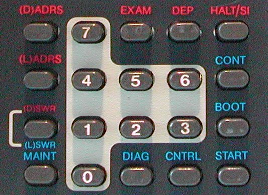 |
| 0,1,2,3,4,5,6,7 | Allows the operator to enter octal data into the display.
The numeric buttons work in Console Mode and in Run Mode.
|
| HALT / SI | Halt / Single Instruction - Depressing
this button while the processor is in Run Mode will halt the processor between instructions, after outstanding trap sequences and
before bus requests. The processor is now in Console Mode and the CONSOLE indicator is turned on.
The octal display indicates the program counter for both HALT and SI functions.
Depressing the HALT/SI button now causes a
single instruction to be executed.To initialize the system without a program start, it is necessary to depress the HALT/SI
button while holding the START button down. |
D(SWR)
*L(SWR) | Display Load Switch Register ,
Load Switch Register
Display the contents of the Console Switch Register in both Console and Run Mode. If this button is
depressed while the CNTRL button is held, the contents of the Temporary Switch Register are loaded into the Console Switch
Register. The contents of the Console Switch Register are displayed. Operative in both Console and Run Modes. |
| (D)ADRS | Displays the contents of the Console Address
Register and clears the DISPLAY LOCK bit, thus enabling the program movements to address 777570. Operation occurs in both
Console and Run Modes. |
| |
| Buttons only active in Console Mode |
|---|
| |
| (L)ADRS | Load Address - Depressing this button
transfers the contents of the Temporary Switch Register to the Console Address Register to be used in subsequent
DEP or EXAM operations. The contents of the Console Address Register is displayed in the octal display and all the
decimal points are turned on. |
| EXAM | Examine - Depressing this button accesses
the UNIBUS address specified in the Console Address Register and displays the contents of that address in the octal
display. Sequential examines increment the address by two and display the contents of the incremented addresses.
This incrementation process is stopped if any other button except numerics is pressed. |
| DEP | Deposit - Depressing this button deposits
the contents of the Temporary Switch Register at the UNIBUS address specified by the Console Address Register. The
Console Switch Register is not changed. To deposit data in sequential addresses, all that is necessary is to press
the DEP button. This automatically word-increments the Console Address Register and deposits the data into the
incremented address.
This process is stopped if any other button except numerics is depressed. |
| *CONT | Continue - Depressing this button allows
the processor to leave the Console Mode and continue operation at the present Program Counter location without
a BUS INIT. The display is unaltered. |
| *START | Start - Depressing this button begins
machine operation at the address (PC) specified by the Console Address Register after a BUS INIT signal. Operation
occurs only in Console Mode and the CONSOLE light is turned off. The display is unaltered. |
| *BOOT | Bootstrap - Depressing this button will
cause a BUS INIT and will start the boot program of the M9301 module. The display is unaltered. |
| *DIAG | Diagnostic - Depressing this button transfers
control to the DCS (Diagnostic Control Store) module, if present. Otherwise, the computer enters Console Mode.
The display is unaltered. |
| *MAINT | Maintenance - This button is used to
read and write the internal registers.
The procedure for reading an internal register is the following.
- Load the Temporary Switch Register with the read opcode of the register that you want to read.
- Depress the (L)SWR button while holding the CNTRL button depressed. This transfers the contents of the Temporary
Switch Register to the Console Switch Register.
- Depress the MAINT button while holding the CNTRL button depressed. The console display will display the contents
of the register specified in the first step.
The procedure for writing an internal register is the following.
- Load the Temporary Switch Register with the write opcode of the register that you want to write.
- Depress the (L)SWR button while holding the CNTRL button depressed. This transfers the contents of the Temporary
Switch Register to the Console Switch Register.
- Load the Temporary Switch Register with the data to be written by depressing the applicable numeric buttons.
- Depress the MAINT button while holding the CNTRL button depressed. The console display will display the data
that has been written into the specified register.
|
back to top
THIS 11/60 SYSTEM CONFIGURATION
|
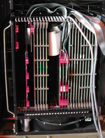
As usual, slot #1 is at the right hand side when you stand in front of the computer. So, from right to left you see the
following system units in my PDP-11/60 processor box.
- PDP-11/60 backplane KD11-K processor boards
- M7870 - KU116 WCS (still empty ...)
- M7872 - KD11-K micro word module
- M7873 - KD11-K decode module
- M7874 - KD11-K data paths module
- M7875 - KD11-K cache memory and MMU
- M7876 - KD11-K timing module
- M7877 - KD11-K status module
- M7878 - FP11-E FNUA (Next micro Address)
- M7879 - FP11-E FLTEXP (Exponent)
- M7880 - FP11-E MULNET (Multiplying Network)
- M7881 - FP11-E FALU (Arithmetic Logic Unit)
- M7856 - DL11-W serial I/O port
- M7856 - DL11-W serial I/O port
- M7856 - DL11-W serial I/O port, system console
- DD11-KF 9-slot 11/60 MOS memory backplane
- DD11-CK 4-slot UNIBUS expansion backplane
|
In the picture you can clearly see the two UNIBUS-out BC11 cables.
One for the connection to the DD11-KF MOS memory backplane, and the other to the DD11-CK I/O peripherals backplane.
In the bottom, below the card cage itself, is a big axial fan that blows cooling air up through the card cage to the rear side.