| RL01 / RL02 removable hard disk drive |
| RL11 / RLV1x controller |
Direct jumps to:
If you want to print this page on A4 or Letter format, set the scaling in the printer driver to 80%.
INTRODUCTION
 For the PDP-11, several models of removable hard disk are available. The ones I have are the older models, but not
the oldest. My PDP-11/35 has two RL02's and one RL01 removable hard disk drive. My PDP-11/35 also has other models of
removable disk drives, the RK05 hard disk and the RX02 dual 8" floppy disk drive.
For the PDP-11, several models of removable hard disk are available. The ones I have are the older models, but not
the oldest. My PDP-11/35 has two RL02's and one RL01 removable hard disk drive. My PDP-11/35 also has other models of
removable disk drives, the RK05 hard disk and the RX02 dual 8" floppy disk drive.
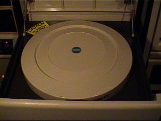
RL01 and RL02 are drives which mounts on slides in the 19" rack. To insert a disk cartridge (which contains one platter)
in the drive, you must pull the drive on its slides out of the cabinet and open the top lid. Remove the disk cartridge
cover and place the disk cartridge in the drive. Place the disk cartridge cover on top of the disk cartridge and close
the lid of the drive.
Push the "LOAD" button. The disk drive will start to spin up the disk cartridge and after some 30 seconds the drive
becomes "READY". Now you can read from and write to the disk.
 On my other system, a PDP-11/34A, I also have two RL02's and one RL01 connected.
The main difference between the two models is the capacity of the media.
An RL01K disk cartridge can hold 5.2 Mbytes of data, whereas an RL02K disk cartridge can hold twice as many: 10.4 Mbytes.
So, let's say, you want some 30 Mbytes of storage. If you are using RL02 drives it would amount to 78 cm height,
102 kilograms and 480 W. power consumption !
On the other hand, it is an impressive view to see that in operation.
After you load the disk you must wait for some 45 seconds before you can access the data on the disk because the disk
must accelerate to 2400 revolutions per minute. Equally, before you can remove the disk cartridge from the drive, the
disk must spin down. This takes about 30 seconds. Locking mechanisms prevent you from trying to take the disk cartridge
out before the drive is spun down.
AVAILABLE DOCUMENTION
- RL01 Disk Subsystem User's Guide (EK-RL01-UG-002)
- RL01/RL02 User Guide (EK-RL012-UG-005)
- RL01/RL02 Pocket Service Guide (EK-RL012-PG-003)
- RL11 Field Maintenance Print Set (MP00153)
(31750 Kb)
- RL01 Field Maintenance Print Set (MP00347)
(rev.C 26400 Kb / rev.D 21698 Kb / rev.F 18676 Kb)
- RL11-AK Field Maintenance Print Set (MP00526)
(3955 Kb)
- RL01-AK Field Maintenance Print Set (MP00527)
(rev.A 2878 Kb / rev.B 2894 Kb)
- RL02 Field Maintenance Print Set (MP00553)
(22493 Kb)
- RL02-AK Field Maintenance Print Set (MP00689)
(2514 Kb)
- RL02-FK Field Maintenance Print Set (MP01332)
- RL01 Disk Drive Illustrated Parts Breakdown (EK-0RL01-IP-003)
- RL01/RL02 Disk Drive Technical Manual (EK-RL012-TM-PRE)
- RLV12 Field Maintenance Print Set (MP01282)
(13725 Kb)
|
Italic size indicates that the document is as TIF file available on request.
|
| |
Back to top
|
GENERAL DRIVE INFORMATION
 Startup current for the RL01/RL02 drive is :
- 3.5 A max at 90 Vac
- 5.0 A max at 127 Vac
- 1.75 A max at 180 Vac
- 2.5 A max at 254 Vac
The power source for the drive is manually selectable at 90-127 Vac or 180-256 Vac.
The power source frequency range is 47.5 thru 63 Hz.
| Drive specifications RL01/RL02 |
|---|
| Height | 26.52 cm (10.44") |
| Width | 19" rack size compatible |
| Depth | 63.5 cm (25") behind bezel |
| Weight | 34 kg (75 lb) |
| Power | 160 W max at 155 Vac, 60 Hz |
|
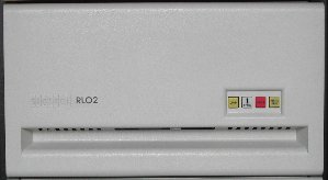
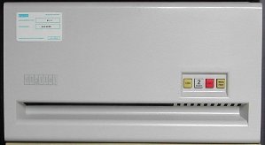
The RL02 diskdrive is the successor of the RL01 diskdrive. The RL02 drive has a label on the front marked "RL02",
the RL01 has no label at all.
Although the RL01K and the RL02K disk cartridge have identical measurements, an RL02K cartridge cannot be read by
a RL01 drive. Likewise, an RL01K cartridge cannot be read by an RL02 drive. A cartridge written by a drive can
(of course) be read by an other drive.
|
The RL02 diskdrive can be modified to accept RL01K disks (read-only!). There are three internal connections that
must be moved. They are located on the R/W board, the logic board and the DC Servo/PSU board.
See "RL01/RL02 DRIVE/PACK COMPATIBILITY" for more information.
| Drive performance (timing) RL01/RL02 |
|---|
| Average latency | 12.5 mSec |
|---|
| Maximum latency | 25.0 mSec |
|---|
| Average seek time | 55 mSec (85/170 tracks) |
|---|
| Maximum seek time | 100 mSec (256/512 tracks) |
|---|
| One cylinder/track seek time | 15 mSec max |
|---|
|
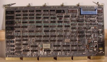
The diskdrive interfaces to the UNIBUS with the M7762 (RL11 controller). From the RL11 controller a flat ribbon cable
with a length of 6 feet connects to a bulkhead assembly. The DEC partnumber is of the cable is BC06R-06.
From the bulkhead a cable, DEC partnumber BC20J, is led to the first drive.
|
An RL11 controller can support up to four drives; a mix of RL01 and RL02 drives is allowed. The BC20J cable is available
in a length of 10, 20, 40 or 60 feet. Total length of cables from the RL11 controller to the last drive must not exceed
100 foot (30 meters). The RL drives are daisy-chain connected, from the first up to the fourth drive. The daisy-chain
is wired pin-to-pin. The last drive in the chain must have the terminator on the outgoing connector. The drives
will not operate without this terminator.
To install the RL01 or RL02 drive in a rack you need two of the slides shown in the picture below.
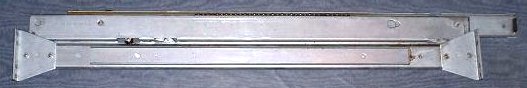 Note that the two slides are not the same! One has an "R" stamped in the slide, the other an "L" ...
HOW TO USE THE RL01/RL02 DRIVE
 Up to four RL drives can be daisy-chained to one controller. It is possible to mix RL01 and RL02 drives at random.
The configuration of the drives, which unit is identified with #0, which is unit #1 and so on, is very simple. Nothing
like setting DIP switches or, even worse, putting jumpers in the correct positions.
Up to four RL drives can be daisy-chained to one controller. It is possible to mix RL01 and RL02 drives at random.
The configuration of the drives, which unit is identified with #0, which is unit #1 and so on, is very simple. Nothing
like setting DIP switches or, even worse, putting jumpers in the correct positions.
To change the number of a drive is as simple as replacing the "READY" indicator with another. Fingers on the backside
of the key cap determine in a binary code whether the unit will become #0, #1, #2 or #3.
If you need another cap you can even modify some caps to another number.
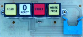
In the situation that the disk drive has no disk cartridge loaded, only the "LOAD" button light is
on. This button must be in the 'out' position. The "WRITE PROT" button light can be on or off.
This depends whether this button is in the 'in' or 'out' position. The "READY" and the "FAULT" light are off.
Procedure to load a disk cartridge.

|
- Slide the disk drive out of the rack.
- Squeeze the knob on the right side of the top cover to open the lid.
- Open the lid gently until the brackets hold the lid open.
- Hold the bottom of the disk cartridge in one hand and move the slider in the handle of the disk cartridge with the
other hand. Lift the handle 90 degrees up. Now you can separate the disk cartridge from the disk cartridge cover.
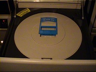
- Place the disk cartridge into the drive. The disk label must be 'at 12:00 hours'.
- Put the disk cartridge handle in the 'down' position.
- Place the disk cartridge cover turned-over on top of the disk cartridge.
- Gently close the disk drive cover until the cover locks.
- Slide the disk drive back into the rack.
- Push the "LOAD" button (to the 'in' position). The light goes off, the disk drive
cover is locked and the disk drive spins up.
- After approx. 45 seconds the "READY" light goes on. The data on the disk cartridge
is available from this moment.
|

|
Procedure to unload a disk cartridge.

|
- Make sure that the system is not reading from or writing to the disk.
- Push the "LOAD" button (to the 'out' position). The "READY" light goes off, and the disk drive spins down.
- After approx. 30 seconds the "LOAD" light goes on. This is the moment that the door lock is released.
- Slide the disk drive out of the rack.
- Squeeze the knob on the right side of the top cover to open the lid.
- Open the lid gently until the brackets hold the lid open.
- Take the disk cartridge cover out of the drive and turn it over.
- With the other hand, lift the disk cartridge handle 90 degrees and take the disk cartridge out of the drive.
- Place the disk cartridge in the disk cartridge cover and put the disk cartridge handle in the 'down' position.
Store the disk cartridge in an appropriate location.
- Gently close the disk drive cover until the cover locks.
- Slide the disk drive back into the rack.
|

|
| RL02 disk drive with cartridge placed | RL02 disk drive with cartridge and cover placed |
|---|
|
|
Note that when an RL drive is powered up, but not connected to the controller, the RED FAULT lamp will be on. The drive
must be connected to the controller and the controller (in the system) must be powered up. The controller supplies a
clock signal to the RL drives and when this clock signal is not present the FAULT lamp is lit. This clock signal is also
used for the speed control circuitry, so without this signal the drive will not spin up.
HOW TO TRANSPORT THE RL01/RL02 DRIVE
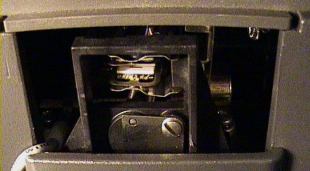
To securely transport a RL0x disk drive you must lock the read/write heads. This is a fairly simple procedure.
To lock the heads you must open the top cover lid. The top cover lid can be opened via a small opening on the right-hand
side of the drive, or, the way I prefer, simple apply power to the drive. You do not need a connection to the controller.
After some time the latch on the top cover lid is released, and then you can open the drive as if you want to place a
cartridge into the drive.
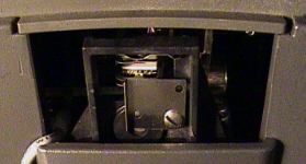
At the opening for the heads you see a small metal plate which is mounted with one screw at the lower right-hand
corner. Loosen this screw, one turn is enough. Place the small metal plate before the opening, and while holding the
plate in place, tighten the screw. The heads are locked now.
When you have moved the drive, and installed it in the rack again, repeat this procedure to move the small metal plate
back to the previous position.
RL01/RL02 DISK CARTRIDGES
 These disk cartridges are factory preformatted: each data track has next to it a servo track which keeps the read/write
head aligned. When you format the disk you only initialize the data tracks. Special equipment is needed to write the
servo tracks. The last track of the last surface is reserved for the cartridge serial number and the bad sector
information.
These disk cartridges are factory preformatted: each data track has next to it a servo track which keeps the read/write
head aligned. When you format the disk you only initialize the data tracks. Special equipment is needed to write the
servo tracks. The last track of the last surface is reserved for the cartridge serial number and the bad sector
information.
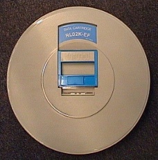
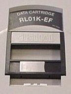
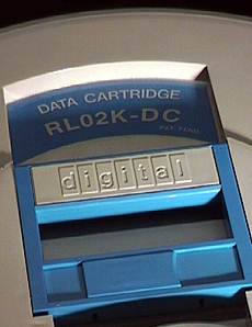
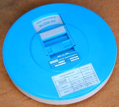
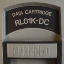
The RL01K and RL02K disk look the same, only the color of the label is different: RL01K disks have a grey label,
RL02K disks have a blue label.
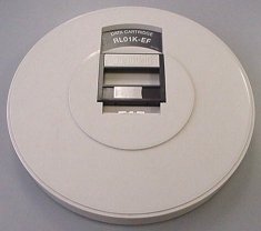
The disk cartridge exist in two versions: with the suffix "-DC" and "-EF". The latter suffix stands for "Error Free";
this EF version is more expensive.
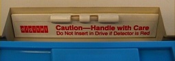
Sometimes the packs have a shock indicator glued on them, mostly near the grip handle. Normally its small tube is
colorless, but when the pack has been dropped or subjected to a shock the indicator is turned red. When this has happened
it is a strong indication to consider some caution when using the disk cartridge in a drive. When the disk platter inside
is distorted by the shock, a head-crash could occur. If you need to extract the data off the disk cartrdige, load the
cartridge in the drive and press the "LOAD" button; the disk starts to spin up. Holding your hand on the drive front
while spinning up could give you a feel of unusual vibrations. Keep your finger on the "LOAD" button! After some 20
seconds the heads loads. When you hear unusual sounds ('pinging') you better immediately press the "LOAD" button again!
The heads will disengage preventing damage. Try to copy the data off the cartridge while keeping your finger on the
"LOAD" button.
What feels and sounds 'normal' is something you get used to over time.
|
|
| Data storage capacity |
|---|
| |
RL01K | RL02K |
|---|
| Number of surfaces | 2 |
|---|
| Number of tracks/surface |
256 | 512 |
|---|
| Track density (per inch) |
125 | 256 |
|---|
| Number of sectors/track | 40 |
|---|
| Number of 16-bit words/sector |
128 |
|---|
| Formatted capacity (Mbytes) |
5.2 | 10.4 |
|---|
Physical dimensions of the disk cartridge:
diameter 38.35 cm (15.1"),
height 6.19 cm (2.44").
|
|
A special cartridge is the "Reference Disk" cartridge.
This cartridge has a clearly visible different color!
The disk is used in the alignment procedure of the RL02 drive.
Actually, it is not the alignment of the heads,
because the RL01/RL02 drives use an embedded servo system.
You can align the heads with *any* normal disk cartridge.
This "Reference Disk" cartridge is an amplitude test pack to check the read amplifier, normally *not* needed.
RL01/RL02 DRIVE/PACK COMPATIBILITY
You cannot read nor write RL01 packs in an RL02 drive or, vice versa, RL02 packs in an RL01 drive.
However, when you change three jumpers inside the drive, you can read packs in the other drive. Writing is
still not possible because the width of the track of the disk is different. An RL02 head writes a smaller width track
on the surface of the platter. These are the jumpers and on which board they are located.
| Board module | W1 jumper | W2 jumper |
|---|
| RL01 | RL02 | RL01 | RL02 |
|---|
| DC Servo module | IN | OUT | IN | IN |
| Drive Logic module | IN | OUT | - | - |
| Read/Write module | IN | OUT | OUT | IN |
|
| Note. All RL02 logic boards can be jumpered to "RL01" mode.
Not all RL01's have the logic boards that have jumpers.
|
RL11 UNIBUS INTERFACE - M7762
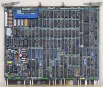
RLV1x QBUS INTERFACE
For the QBUS machines there are two interface versions available :
- RLV11
This interface consists of two quad-sized boards, M8013 and M8014.
The boards can be installed in Q/CD only slots, next to each other. The RLV11 supports 18-bit DMA only.
Warning: the RLV11 uses BC1 and BD1 connections to the backplane for purposes other than BDAL18 and BDAL19.
- RLV12
This is the newer type disk controller, it is one quad-sized board, M8061.
more to be added ...
RL INTERFACE - DRIVE CONNECTION
 No matter what bus interface you have (UNIBUS RL11 or one of the QBUS variants RLV1x), the connection to the drive
consists of the following parts.
No matter what bus interface you have (UNIBUS RL11 or one of the QBUS variants RLV1x), the connection to the drive
consists of the following parts.
- flatcable from the controller module (BERG connector) to the bulkhead in the rack.
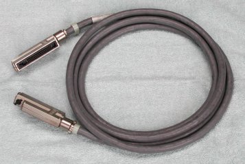
- round cable (BC21Z-xx or 70-12122-xx) from bulkhead to the first drive IN connector. This cable
is also used to connect all other RL01/RL02 drives (max 4 drives, and RL01 / RL02 can be mixed). The "xx" in the cable
number stands for the length in feet. A common value is 10. The connector has 40 pins.
- terminator on the last drive in the chain, on the OUT connector.
The picture at the right shows a 10-feet cable with metal caps for the connector.
The cable also exists with black plastic caps.
A small black "knob" on top of the end of the connector latches the connector to its counterpart on the drive or the
bulkhead by rotating it 90 degrees.
top view
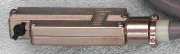
pin view

terminator
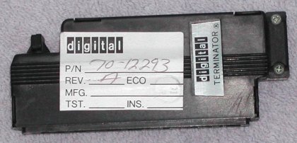 |
Note that this cable looks like the cable to connect RK06/RK07 drives. However,
the part number for the RK06/RK07 cable is 70-12292-xx, uses the same connector, but more pins are actually
connected in the cable. The 70-12122-xx cable does not connect all pins! So, you can use the RK06/RK07 drive cable
to connect RL drives, but not the other way around.
The terminator used for the RL01/RL02 and the RK06/RK07 drives is identical. |
RL DRIVE TROUBLE SHOOTING TIPS
One important thing to remember is that the RL drive needs a clock signal which is provided by the controller.
You can power up a drive without a connection to the controller, but the FAULT light will turn on.
This is also the behaviour if you power up the drive but do not power up the system in which the controller is installed.
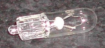
So, your first check is testing the four light bulbs in panel. Simply pull the READY out of the panel,
and pull the other three caps off (apply a little force on the top side of the cap). The light bulbs used in the RL01/RL02
front panel have number #73, and are rated 14 Volt. The light bulbs used in the RA81 front panel look the same, but have
number #86. When this number is not telling you anything, the rating for that bulb is 6.3 Volt. Use a pair of squeezers
to pull the bulbs out of their sockets (wedge-ended all-glass bulbs). An Ohm-meter will tell you ...
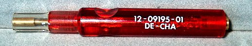
DIGITAL even had a lamp insertion & extraction tool for these small bulbs. Its part number is 12-09195-01, and
it is approx. 3.75" long.
The left part is flexible tubing to grab the bulb, and a metal shaft through the tool can push a bulb into its socket.
Connect the RL drive IN connector with the cable to the controller and install a terminator on the
OUT connector on the drive. When you power-up the system (in which the controller is installed) and
you apply power to the drive, the FAULT light should not turn on continuous. It may be lit for a short
part of a second when the power comes up, but if all is OK the FAULT light must be off.
If you power down the drive, disconnect the cable between the controller and the drive, and power up again, the
FAULT light turns on.
If the FAULT light goes on in other conditions you need to find out why.
If the FAULT light stays off you can load a cartridge as described in "Procedure to load a disk cartridge".
You can hear the spindle motor of the drive accelerate, put your ear on the top lid! When the drive reaches the nominal speed
the heads come out and try to find the outer track. So, if the heads do not load suspect the drive spindle area.
If the heads load the drive tries to read data from the outer track. If this operation is succesfull the READY
light goes on. If the READY light remains off you might have loaded a bulk-erased cartridge. Very painfull
to say, but that cartridge is worthless, because without very sophisticated equipment you can not format the cartridge! The
cartridge also has the servo tracks written on the platter, and I have read that the equipment to format the platters has
an interferometer for the proper alignment ...
Sometimes the drive comes to READY without the terminator installed at the end of the chain of drives,
but it is also possible that the drive just spins up and the READY never lights ...
An other possibility is that the heads do not load, because the mechanical lock in front of the heads is in place to lock
the heads for shipping. Make sure that this plate is not for the opening of the heads! See the section
"How to transport The RL01/RL02 drive".
CONTROLLER DIAGNOSTICS
 The RL11 (M7762) UNIBUS interface has two diagnostics.
| «-»
| ZRLG(x) | RL11 controller test 1 |
| «-»
| ZRLH(x) | RL11 controller test 2 |
The following diagnostics are for the disk cartridges.
| «-»
| ZRLI(x) | RL01 / RL02 drive test 1 |
| «-»
| ZRLJ(x) | RL01 / RL02 seek test |
| «-»
| ZRLK(x) |
RL01 / RL02 performance exerciser |
| «-»
| ZRLL(x) | RL01 / RL02 compatibility |
| «-»
| ZRLM(x) |
RL01 / RL02 bad sector file utility |
| «-»
| ZRLN(x) | RL01 / RL02 seek/read |
The (x) represents the version.
This is a single letter for the revision level, and one single digit for the patch level.
There are also some earlier diagnostics, but these cover only RL01 drives and RL11.
| ZRLA(x) | Controller Test Part 1 |
| ZRLB(x) | Controller Test Part 2 |
| ZRLC(x) | Drive Test Part 1 |
| ZRLE(x) | Drive Test Part 2 |
| ZRLE(x) | Performance Exerciser |
| ZRLF(x) | Compatibility Test |
There are also a pair of diskless tests developed specifically to cope with the differences between
UNIBUS and QBus controllers.
| VRLA(x) | Diskless Test 1 |
| VRLB(x) | Diskless Test 2 |
RL11 (M7762) BOOTSTRAP DATA
Loading or toggling in this data enables the PDP to boot from the RL disk.
This bootstrap is taken from the RT-11 V5.5 installation manual.
I have entered this code and my PDP-11/34A and PDP-11/35 just boots fine.
How to load a bootstrap program and start the execution on a PDP-11/35 or PDP-11/40.
How to load a bootstrap program and start the execution on a PDP-11/34(A).
The start address is 001000.
| | x0 | x2 | x4 | x6 |
|---|
| 001000 | 012701 | 174400 | 012761 | 000013 |
|---|
| 001010 | 000004 | 012711 | 000004 | 105711 |
|---|
| 001020 | 100376 | 005061 | 000002 | 005061 |
|---|
| 001030 | 000004 | 012761 | 177400 | 000006 |
|---|
| 001040 | 012711 | 000014 | 105711 | 100376 |
|---|
| 001050 | 005007 | | | |
|---|