| PC05 High-Speed Paper-Tape Reader / Punch |
| PC11 controller |
Direct jumps to:
If you want to print this page on A4 or Letter format, set the scaling in the printer driver to 80%.
INTRODUCTION
 The PC05 is a paper tape reader and (optional) paper tape punch unit.
The PC05 unit is mounted in a 19" standard rack, and has its own interface to connect to the PDP-11 computer.
The interface is called PC11 and it is only available for UNIBUS systems.
I have two PC05 units in my collection, one is connected to the PDP-11/35, the other is connected to the PDP-11/20.
AVAILABLE DOCUMENTATION

- PC11 reader/punch control engineering drawings TIF file (7536 kB)
- PC04/PC05 paper tape reader/punch engineering drawings TIF file (29014 kB)
Available on "bitsavers" :
- PC04/PC05 paper-tape reader/punch (feed-hole strobed)
PDF file DEC-00-PC0A-D_PC04_Manual.pdf 2760 kB
- PC11 high speed reader/punch and control manual
PDF file PC11_Reader-Punch_Manual.pdf 1629 kB
Available on "Manx" :
- PC11 reader/punch control engineering drawings
PDF file PC11.pdf 6724 kB
GENERAL PAPERTAPE READER/PUNCH INFORMATION
| PC05 Paper-Tape drive specifications |
|---|
Physical
dimensions |
Height: 10.5 in.
Width: 19 in.
Depth: 15 in. |
Power
requirements |
115 VAC +/- 10% @ 50 or 60 Hz |
Power supplies
(internal) |
Regulated, -15V +/- 1 V
Regulated, +5V +/- 0.25 V
Unregulated, -36V +/- 4V |
| Logic levels |
Logic "1" (H) | +2.0V , input
+2.4V , output |
Logic "0" (L) | +0.8V , input
+0.4V , output |
Paper tape
characteristics |
Reader: Gray, unoiled, fan-folded, transmittance up to 12%.
Punch: Oiled or unoiled, fan-folded. |
Tape tension
(in punch) |
6 oz, maximum |
|
|
The PC05 High-Speed Paper-Tape Reader/Punch (as it is officially called) can be controlled by any PDP-11 System through a PC11 Reader/Punch Control. The PC05
serves as an input device (from eight-channel, 1 inch, perforated paper tape) and an output device (to the same medium) for the system.
Two variations of the PC11 device are available from Digital Equipment Corporation (DEC). The PC11-A is designed for 50 Hz power. The PR11 is a reader
without a punch; it uses equipment identical to the reader portion of the PC11.
When a 240 Volt power supply provides power to any of these devices, a step-down transformer (H722) must be connected between the mains power and the PC05 power supply.
The PC05 combines a photoelectric paper-tape reader and an electromechanical paper-tape punch in a 10�" high frame that mounts in a standard 19" rack.
|
| The following model variations exist : |
o PC05R
o PC05P and PC05PA
o PC05C and PC05CA
|
- Reader only unit
- Punch only unit
- Reader and Punch unit
|
The "PA" and "CA" models are 50 Hz models. The 50 Hz and 60 Hz models are identical, with the exception of the punch pulley. |
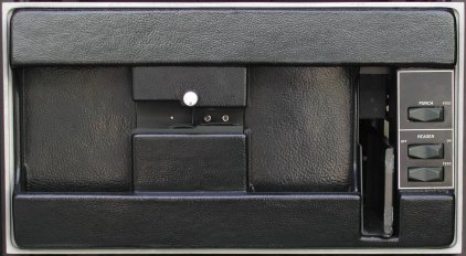
Controls
The PC05 papertape reader/punch unit has manual power controls and manual feed switches, located on the front panel, for operation of the tape advance feature of both the
reader and punch. All other operations of the PC05 are program-controlled.
| Reader |
OFF LINE / ON LINE | When this switch is placed in the ON LINE position, the computer is
allowed to control the reading of papertape. |
|---|
| FEED | When this spring-loaded switch is pressed, the reader control is enabled and the papertape advances through the read head without
actually reading. |
|---|
| Punch |
FEED | When this spring-loaded switch is pressed, the punch drive motor is switched on and blank tape is punched (only the feed hole is
punched). This switch overrides a punch command from the processor. It is used to punch leader tape. |
|---|
PC05 DETAILED INFORMATION
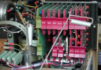
 The PC05 contaions a small card cage with the following modules :
- G918 - Photo Amplfier
- M040 - Solenoid driver
- M044 - Solenoid driver
- M7050 - Reader Control
- M710 - Punch Control
- M715 - Reader Clock
Connections to the punch unit and the photo read head are made to the card cage with paddle connector boards. Likewise, paddle boards are used
for the connection cables to the PC11 interface. See the figure for the correct position of the paddle boards.
Note. As you can see in the picture (click the thumbnail below), the orientation of the backplane (and FlipChips)
inside the PC05 is different from the drawing in the manual.
The PC05 contains its own power supply and control and drive circuitry (the control circuitry for the PC04 is contained in the CPU).
The tape reader mechanism is manufactured by DEC and contains an electromechanical tape-feed system, with associated current drivers, and a nine-channel photoelectric
tape-read head, including photocell amplifiers. Information is read from 8-level, 1 inch perforated tape, at a maximum of 300 characters per second (continuous), or at a
single character rate of 20 characters per second.
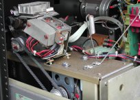
The tape punch mechanism is a Roytron Model 500 modified by DEC. Contained in the unit is an electromechanical tape feed and punch system capable of punching five-,
seven-, or eight-level tape. An SCR driver is included that switches the AC power to the punch motor after a command to punch is received.
"PDP" PAPER TAPE
Papertape was (and still is!) a reliable storage medium of programs and data. I don't know a computer manufacturer that did not have a
papertape reader and punch in its sales brochure. There were many independent vendors of such units, for example Remex, Ghielmetti,
and Facit.
I am sure there were others! You may see papertape readers still in action near CNC machines, but nowadays these CNC's
often have a direct serial connection to a computer. The joke often heard is that punching papertape has a big advantage over other
media, because you automatically get a back-up of the punched information (the chad in the chad box).

The paper tape processed by the PC11 Reader/Punch is 1 inch wide, eight-channel tape. Each byte of data is punched into one frame that
consists of 8 data positions arranged in a line perpendicular to the length of the tape. A hole punched in a data position represents
a logic "1", the absence of a hole represents a logic "0".
The data positions are numbered 0 to 7, with 0 the least significant
bit and 7 the most significant bit. The feed hole, which is punched for every frame, is positioned between channels 2 and 3.
The picture shows 8-level punched papertape. The feed hole is also punched as the tape moves through the puncher. The represented
value is 105 (octal).
The puncher of the PC05 can punch oiled papertape and unoiled papertape. However, the punch needs periodically oiled papertape for
lubrication of its mechanism.
Loading of tape in the PC05
- Loading a new box of tape in the PC05 punch
- Pull the PC05 unit straight out of the rack on its drawer slides.
Then flex the tape-feed bracket and remove the exhausted tape supply carton.
- Press the punch FEED switch until the stub end of tape stops moving out of the PC05.
- Pull the stub out of the exit slot.
- Install a new carton in the tape well provided on the rear of the tape punch chassis.
- Feed the new tape out of the carton, with the printing face-down.
Route the tape through the two rollers, over the out-of-tape switch and guide
plate, directly into the punch block.
- Guide the tape out over the sprocket and down through the feed-chute tray.
- Press and hold the punch FEED switch until several folds of tape are present in the bin.
It is necessary to stack the first
few folds by hand to guarantee proper stacking.
- It is good practice to empty the chad box whenever a new box of tape is loaded.
Under certain conditions, such as low humidity, chad tends to build-up in the plastic punch cover and subsequently the punch assembly.
This condition can be avoided by dipping the plastic punch cover in an anti-static solution.
- The punch should be oiled monthly by running a box of oiled tape through it while punching all 1s.
See the "Diagnotic programs" section" for an alternating ones and zeroes test tape generation program.
- Loading punched tape in the PC05 reader
- Raise the tape depressor and load the tape into the right-hand bin.
Thread the tape under the tape hold-down bracket.
- Place the tape on the sprocket teeth and lower the tape depressor fork.
Press the reader FEED switch.
Run the tape leader
into the left-hand bin and dress the tape folds.
PC11 UNIBUS INTERFACE
The PC11 High-Speed Paper-Tape Reader/Punch and Control (UNIBUS) interface for the PC05 exists in two variations.
The first version is built from several FlipChips: M781 (dual width), called PC11 control, and the standard FlipChips M105 (device address selection)
and M782 or M7821 (interrupt control). The more modern version of the PC11 is the M7810 which holds on a single quad width module the entire interface
for the PC05. As far as I know, no QBUS interface for the PC05 exists.
The PC11 controls the PC05 and can operate the PC05 for single data transfer or continuous data transfer.
| PC11 interface |
|---|
| version | module | position |
|---|
| old version | M781 | pos. C-D |
|---|
| M105 | pos. E |
| M782 | pos. F |
| new version | M7810 | pos. C-F |
|---|
The PC11 quad-sized module can be installed in any SPC (Small Peripheral Connector) slot, for example the 4-slot DD11-A or 9-slot DD11-DK backplane.
The M7810 module can also be installed in slot #13 or slot #14 of the PDP-11/20 CPU backplane, as these two slots are wired as a DD11-A equivalent.
The old version of the PC11 is also listed in the table, for completeness.

Each PC11 uses 4 device register addresses, 2 interrupt vector address pairs, and a bus priority level assignment. The default base register address
is 777550, reader interrupt vecor is 70 and the punch interrupt vector is 74. These values can be changed by modifying the jumper settings. The bus
priority level is determined by a request and grant jumper plug. The M7810 module is normally supplied with a jumper plug that provides a BR4
priority level. The reader has a higher priority level than the punch if both request service simultaneously, because the bus grant signal must pass
through the reader interrupt logic before reaching the punch interrupt logic.
Configuration jumpers on the M7810
- Address selection
Address line A00 is used for byte control, and address lines A01 and A02 are used for addressing the device registers. The high address lines A17 thru A13
must all be "1"s. This specifies an address within the top 8K byte address bounds for device registers.
Address lines A12 thru A03 are used in the address selection in the PC11. When an address selection line contains a jumper, the address bit should be "0",
if there is no jumper, the address bit should be "1" for device activation. For the standard (base) address 777550, this means a jumper in bit positions
4 and 7.
| Note. Connection of the jumpers on the quad-sized module M7810 is identical to the method used on the earlier
version of the PC11, where address selection is configured on the single-sized M105 Address Selector Module. |
- Interrupt vector
The normal vector address for the PC11 is 70 for the reader, and 74 for the punch. Six jumpers select the address vector. The least significant digit
of the vector address is set by the jumper in bit 2, so all vector address end in either 0 or 4. A jumper installed represents a logic "1", no jumper
represents a logic "0". For the standard vectors addresses this means a jumper in the bit positions 3, 4, and 5.
| Note. Connection of the jumpers on the quad-sized module M7810 is the reverse of the method used on
the earlier version of the PC11, where interrupt vector selection is configured on the single-sized M782 or M7820 Interrupt Control Module. However,
it is identical on the M7821 module. |
The interrupt logic used in the PC11 is not capable of issuing NPR requests. In order to improve NPR latency in the computer sustem, the NPR line is
sampled and prevents an interrupt request until all NPRs have been honored by the system. The sampling of the NPR line is controlled by jumper N1 on
the M7810. Only certain PDP-11 processors can work with the special circuit described. The jumper N1, when cut, prevents the special circuit from working.
INSTALLATION
The PC05 can be used with several different computer systems (PDP-11, PDP-12, and PDP-15). Therefore, a specific mounting procedure cannot be given.
The unit is normally mounted in the central processor cabinet, above the console panel. The PC05 can, however, also be mounted in an accessory cabinet.
(Remark: the PC04 is used with PDP-8I, PDP-8E and PDP-8L).
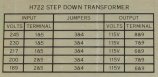
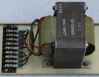 The power supply for the PC05 is always 115VAC. If the mains power voltage is different, the H722 step-down transformer must be installed in the
rear of the cabinet. Taps are available on the transformer to match the voltage of the mains power, see the label affixed on thet metal mounting plate.
The power supply for the PC05 is always 115VAC. If the mains power voltage is different, the H722 step-down transformer must be installed in the
rear of the cabinet. Taps are available on the transformer to match the voltage of the mains power, see the label affixed on thet metal mounting plate.
The transformer is connected between the mains power (switched output from the power controller) and the PC05 power supply socket.
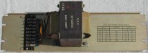
Click the thumbnail pictures to see a larger picture of the transformer on its original mounting plate with the table of connection tabs,
and a detailed picture that shows the connection tabs table.
Connection tab #1 is the lowest terminal in the picture, an orange wire goes from that terminal to the transformer. Connection tab #9
is the upper terminal in the picture, a green wire goes from that terminal to the transformer.
|
|
The PC05 Paper-Tape Reader/Punch unit connects to the PC11 UNIBUS interface module with two BC08J cables.
The BC08J cable is tied to an M953 Connector Module that plugs into the PC05, and a Berg (IDC) connector that plugs into the M7810 module. The READER
cable plugs into slot B09 in the PC05 and the PUNCH cable plugs into slot B10 in the PC05 (see section "PC05 detailed information"). The Berg
connectors are labeled "READER" and "PUNCH" on the M7810.
Checkout after installation
After the PC05 has been installed, proceed as follows to checkoput the unit.
- Apply power to the computer system and turn on the punch and reader.
- Load a new carton of tape in the punch unit wll, located at the rear of the chassis, and feed the tape through the punch unit.
- Press the punch FEED on the front panel of the PC05.
Tape should feed out of the tape slot and should be unpuinched except for feed holes.
- Hold the punch FEED switch pressed until a few feet of tape have been punched.
Tear off the tape and insert it in the reader head,
feeding from left to right.
- Press the reader FEED switch and observe that the tape feeds evenly without binding on the edges of the tape guide.
- Load and run the applicable MAINDEC diagnostic test, using the instructions contained with the diagnostic test.
Preventive maintenance
Under normal environmental and work-load conditions routine preventive maintenance should be performed after every 600 hours of operation (or every 4 months,
whichever occurs first). This schedule should be modifed when extreme temperature, humidity, dust, or work-load conditions exist.
- Mechanical checks
- Visually inspect the genral condition of the tape reader.
- Clean the interior and exterior of the tape reader, using a vacuum cleaner or a clean cloth that has been moistened with a nonflammable solvent.
- Lubricate the chassis slide mechanism with a light machine oil. Wipe off excess oil.
- Inspoect all wiring and cables for any damage and mechanical security.
- Inspect the following components for mechanical security: reader FEED switch, reader ON/OFF LINE switch,
light condensor, phototransistor assembly, depressor arm, hold-down bracket, all connectors and circuit modules, tape feed motor, front cover and
resistor assembly.
- Electrical checks
Perform the power supply output checks described in the table. With the normal load connected, use a multimeter to measure the output voltages and an
oscilloscope to measure the peak-to-peak ripple content on all DC outputs of the power supply. The +5 VDC and -15 VDC supplies are adjustable. The
-18 VDC and -36 VDC supplies are not adjustable.
| Output voltage | +5V +/- 0.25V | -15V +/- 1V | -18V +/- 2V | -36V +/- 4V |
|---|
| Ripple (peak-to-peak) | 0.1V | 0.1V | 1.0V | 1.0V |
| Pin number on PC05 | A1A2 | A1B2 | B8V2 | A8V2 |
DIAGNOSTIC PROGRAMS
The PC11 subsystem has just one diagnostic reader test program for the PDP-11 computers, called MAINDEC-11-D2BA.
| Name | Address | Mnemonic | Function |
| Reader Status Register | 777550 | PRS | Provides indications of reader status, controls
interrupts by the reader, and inititates reading. |
| Reader Buffer Register | 777552 | PRB | Read-only register that gates data from the reader.
Information is in low byte. |
| Punch Status Register | 777554 | PPS | Provides indications of punch device status and
controls interrupts by the punch. |
| Punch Buffer Register | 777556 | PPB | Write-only gating to the punch. Punching begins
when the buffer in the punch is loaded. |
|
The PC11 has 4 device registers mapped to 4 sequential words in memory. The addresses are determined by jumpers on the M7810, see the table.
- PRS - PC11 Reader Status register (777550)
| bit | Designation | Description and Operation |
|---|
| 00 |
RDR ENB |
Reader Enable, write only. Always read as a 0. If a 1 is loaded into this bit, a read cycle is started, BUSY is set, DONE
is cleared, and the PRB is cleared. |
| 06 |
RDR INTR ENB |
Reader Interrupt Enable, read/write. Cleared by INIT. When this bit is set, DONE or ERROR becoming set starts an interrupt sequence. |
| 07 |
DONE |
Read-only. This bit is set when a new data byte is available and cleared when RDR ENB is set, or the PRB is read,
or an INIT signal occurs. If RDR INTR ENB is also set, an interrupt sequence is started. |
| 11 |
BUSY |
Read-only. This bit is indicating that the reader is completing an operation. BUSY is set when RDR ENB is set, and
cleared when the present operation is complete (DONE set). |
| 15 |
ERROR |
Read-only. This bit is set to indicate that one of the following conditions has occurred : a) reader out of tape,
b) reader off-line, c) no power to reader. This bit starts an interrupt sequence if RDR INTR ENB is set. If the error condition
has not been cleared manually, and an attempt to set RDR ENB is made, an immediate interrupt occurs, and no operation is initiated. |
- PRB - PC11 Reader Buffer register (read only) (777552)
The bits 07 - 00 of this register transfer eight bits of data from the PC05 reader to the UNIBUS.
The register is read-only; it responds to DATO operations, but the contents of the register are unchanged. The most significant bit of the register is bit 07,
and the least significant bit is bit 00.
- PPS - PC11 Punch Status register (777554)
| bit | Designation | Description and Operation |
|---|
| 06 |
PUN INTR ENB |
Punch Interrupt Enable, read/write. Cleared by INIT. When this bit is set, either READY or ERROR can start an interrupt sequence. |
| 07 |
READY |
Read-only. This bit signifies that the punch can accept a byte for transfer to the paper tape. This bit is set when the current
operation is completed, or by INIT, and cleared when the PPB is loaded. This bit starts an interrupt sequence if PUN INTR ENB is set. |
| 15 |
ERROR |
Read-only. This bit indicates that one of the following conditions has occurred : a) punch out of tape,
b) no power to punch. If PUN INTR ENB is set, this bit causes an interrupt. If an attempt to punch a character is made before the error condition
has been manually corrected, an immediate interrupt can occur. |
- PPB - PC11 Punch Buffer register (write only) (777556)
Loading a byte into the PPB register clears READY in the PPS register and begins a new cycle of punch operation. The contents of the PPB register cannot be read
to the UNIBUS. The most significant bit of the register is bit 07, and the least significant bit is bit 00.
Program to generate an alternate ones and zeroes test tape
| Address | Octal data | Mnemonic | Operand(s) |
| 200 | 012737
177777
177556 | MOV | #177777,@#177556 |
| 206 | 105737
177554 | TSTB | @#177554 |
| 212 | 100375 | BPL | .-4 |
| 214 | 012737
000000
177556 | MOV | #0,@#177556 |
| 222 | 105737
177554 | TSTB | @#177554 |
| 226 | 100375 | BPL | .-4 |
| 230 | 000137
000200 | JMP | START |
PC11 BOOTSTRAP DATA
The following information is copied from PDP-11 Bootstrap Loaders.
| "xx" | memory size |
|---|
| 017744 | 4k |
| 037744 | 8k |
| 057744 | 12k |
| 077744 | 16k |
| 117744 | 20k |
| 137744 | 24k |
| 157744 | 28k |
|
| "xx" value depending on memory in system |
The paper tape bootstrap is a two stage process. First the bootstrap loader must be toggled in at the appropriate location (see table for "xx").
A special bootstrap tape (in Absolute Loader format) must be in the reader with the leader (punch 351) in the read frame. The program is then
started at location xx7744. Note that the program is self-modifying, so if you read the wrong tape, or position it incorrectly, it will corrupt
itself. The program halts when the last frame of the loader is read. Then, put in the tape you want loaded (on blank leader) and press continue
or start at xx7500.
    Location   Contents   Label     Instruction           Comment
    ============================================================================
    xx7744      016701              mov    device,r1      get CSR address
    xx7746      000026
    xx7750      012702    loop:     mov    #offset,r2     get offset
    xx7752      000352    offset:
    xx7754      005211              inc    (r1)           read frame
    xx7756      105711    wait:     tstb   (r1)           wait for ready
    xx7760      100376              bpl    wait
    xx7762      116162              movb   (r1),bnk(r2)   store data
    xx7764      000002
    xx7766      xx7400
    xx7770      005267              inc    offset         bump address
    xx7772      177756
    xx7774      000765              br     loop
    xx7776      177550    device:                         CSR of PC11
                                                          or 177560 for teletype
How to load a bootstrap program and start the execution.