| TS03 tape drive |
| TMB11 controller |
Direct jumps to:
If you want to print this page on A4 or Letter format, set the scaling in the printer driver to 80%.
INTRODUCTION
The TMB11/TS03 DECmagtape System is a magnetic tape storage system that interfaces with the PDP-11 UNIBUS
systems. The TMB11/TS03 reads and writes data in 9-channel, 800 bpi, industry-compatible NRZI format.
The DECmagtape System consists of the TMB11 Controller and the TS03-M Master Tape Transport. The master tape transport is in fact
a slave tape transport with an M8920 Adapter module. A second slave transport (TS03-S) can be added that connects to the module
in the master tape transport.
The TMB11 Controller interfaces the DECmagtape System tot the PDP-11 UNIBUS.
The Controller controls the data transfers, issues control commands to the TS03 master, and monitors system operation. Each
TMB11 Controller can control two TS03 transports, a master and a slave.
The M8920 processes commands from the Controller and issues motion and read/write commands to the master and the slave transports.
The M8920 also monitors status lines from the master and the slave transports. Any status changes at the selected transport
are reported immediately to the Controller.
The tape transport is a single, rack-mounted drawer with the M8920 Adapter module mounter underneath the master transport.
AVAILABLE DOCUMENTION
- TMB11 Field Maintenance Print Set (MP00078)
- TS03-M Engineering Drawings (Rev. A)
- TS03-TU10-M interface schematics M8920
- TS03-M Master drive unit
- TS03-S Slave drive unit
- TS03-M Master dribve unit (ECO TS03-M-0001)
- TMB11/TS03 DECmagtape system maintenance manual (TMB11-M system) (EK-TMB11-MM-001)
- TMB11/TS03 DECmagtape system user's manual (TMB11-M system) (EK-TMB11-OP-001)
GENERAL TAPE TRANSPORT INFORMATION
The tape transport is available in 2 models, TS03-xA and TS03-xB. The "A" version is for 115VAC 60 Hz primary power, and the
"B" version is for 230VAC 50Hz. The "x" denotes with the letter "M" the master transport, and the letter "S" the slave transport.
The master transport requires for the M8920 additionally +5 Volt (3 A. max) and the AC LO signal.

| TS03 Specifications |
|---|
| Reel diameter | 7 inches (17.8 cm) |
| Tape length | 600 ft (182.9 m) |
| Storage capacity / reel | 5 million characters |
| Number of tracks | 9 |
| Recording density / method | 800 bpi / NRZI |
| Data transfer speed | 10,000 char/sec |
Tape motion
read/write speed
rewind speed
start / stop distance
start / stop time |
12,5 inch/sec
75 inch/sec (rewind max time = 2 minutes)
0,19 inch (0.48 cm)
30 msec |
Power requirements
TMB11
M8920
TS03
Input power |
5 A. at +5 VDC
2 A. at +5 VDC
1 A. at 90...132 VAC or 0,5 A. at 180...264 VAC
240 W at 115 VAC, 120W at 230 VAC |
| Tape drive, size | height 10,5 inch (26.7 cm), 17 inch (43 cm) deep |
| Tape drive, weight | 37 lb (16.7 kg) |
The magnetic head is a dual-gap, read after write type, 0,15 inch (0.4 cm) gap. Broken tape, BOT, and EOT detection are
photoelectric. BOT and EOT detection require a reflective strip on the magnetic tape.
MAGNETIC TAPE
Care of magnetic tape
Just as with diskettes, disks and other storage media there are some guide lines of use.
- Do not expose magnetic tape to excessive heat or dust.
Most tape read errors are caused by dust or dirt on the read/write
head. It is important to keep the tape clean.
- Always store the tape reels inside the containers when the tape is not in use.
Keep empty containers tightly closed to
guard against dust and dirt.
- Never touch the portion of tape between Begin (BOT) and End-Of-Tape (EOT) markers. Oil from fingers attract
dust and dirt.
- Never use a contaminated reel of tape. This spreads dirt to the clean tape reels and could adversely affect tape
transport reliability.
- Always handle tape reels by the hub hole. Squeezing the rell flanges leads to tape edge damage when winding or unwinding
tapes.
- Do not smoke near the tape transport or storage media. Smoke and ash are especially damaging to tapes.
- Do not put magnetic tape near lineprinters or other devices that produce paper dust.
- Do not put magnetic tape in any location where it may be affected by hot air.
- Do not store magnetic tape near electric motors or any other magnetic sources that may erase data.
 Write protection
Before you mount the reel of tape onto the supply hub, determine if you must write data to the tape.
If write operations are to be performed, you must put a write-enable ring into the bottom recessed portion of the reel.
When the write-enable ring is not installed you can not write data to the tape. The tape is "write protected".
Reflective tape markers
Every reel of magnetic tape must have a BOT and an EOT reflective marker, so that the transport can recognize starting and
stopping areas. Tapes are always supplied with reflective markers installed. However, if the markers become detached for any
reason or, if a tape leader is shortened because of tape damage, then the operator must install a marker at the position
as shown in the figure below.
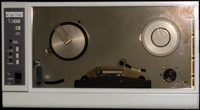
OPERATION & TROUBLESHOOTING
 The TS03 tape transport has a small control panel at the left side of the unit. At the bottom is the ON/OFF switch which
applies AC power to the unit. From top to bottom you have the following indicators and buttons.
The TS03 tape transport has a small control panel at the left side of the unit. At the bottom is the ON/OFF switch which
applies AC power to the unit. From top to bottom you have the following indicators and buttons.
- UNIT SELECT
This is a small plug which designates the transport as unit 0 or as unit 1. In a single drive system, the drive is always
designated drive0. In a dual drive system, either drive can be designated as drive 0. The unit select plugs are the same
plugs as used on th TU10 tape transport and the RM03 removable cartridge disk drive.
- WRITE ENABLE
This is an indicator which is ON whenever a tape reel is mounted with a write-enable ring installed on the supply hub.
- ON LINE
This is a push button and an indicator. The momentary push-button which functions as alternate action. When first activated,
the tape unit is placed in an on-line condition. When the tape unit is on-line, it can be remotely be selected and will
be ready if tape is loaded to or past the load point. When activated again it takes the unit off-line. The indicator is
ON in the on-line condition. The load function must be performed before the unit will go on-line.
- LOAD
This is a push button and an indicator. The momentary push-button activates the reel servos (tensions the tape) and starts
the load sequence. The indicator is ON when the reel servos are activated and tape is tensioned.
- REWIND
This is a push button and an indicator. The momentary push-button activates a rewind operation. This control is enabled only
when tape is tensioned and the unit is off-line. The indicator is ON during either a local or a remote rewind operation.
Mount a tape
 To thread the tape, do the following steps.
- Raise the latch of the quick-release hub and place the reel of tape on the supply hub. If you want to write data to the
tape, install a write-ring at the rear side of the tape reel.
- Hold the reel against the hub flange and press the hub latch down to secure the reel.
- Thread the tape along the path as shown in the figure.
- Holding the end of the tape with a finger, wrap a few turns of the tape counterclockwise around the take-up hub.
Load a tape
Pressing the LOAD button energizes the reel servos and initiates a load sequence. Tape advances to the load
point marker and stops. If for some reason the load point marker is already past the sensor (as for example, in restoring power after
a shutdown), tape will continue to move. Under these conditions, press LOAD and then REWIND
and the tape will rewind to the load point. Once pressed, the LOAD switch is illuminated and is inactive until
power has been turned off or the tape is removed from the unit.
Place the tape unit on-line
After the tape has been properly threaded and has been loaded and moved to the load point, press the ON LINE
button and check that the ON LINE indicator is ON. The REWIND button is disabled when the
tape unit is on-line. The on-line status enables the tape unit to be remotely selected and to perform all normal operations
under remote control.
Rewind and unload a tape
The tape can be rewound to load point under remote control. However, you can do this operation also manually as follows.
- If the ON LINE indicator is illuminated, press the ON LINE button. Check that
the ON LINE indicator goes OFF.
- Press the REWIND button. The tape will now rewind to the load point marker.
- After the tape has been positioned at the load point under remote or manual control, the tape can be unloaded by pressing
the REWIND button again to rewind the tape past the load point to the physical beginning of the tape.
Remark. You can not stop the rewind sequence until the tape has rewound either to the load point or until the tension is
lost at the physical beginning of the tape.
Power shutdown
Press the POWER ON/OFF switch to OFF to remove AC power from the transport. You should not turn off the
tape transport when a tape is loaded and is past the load point marker. The TS03 is designed to prevent physical damage to
the tape in the event of power failure, and to minimize operator error that could destroy recorded data. In the event of
power failure during tape operation, manually wind the tape forward several feet before restoring power. When power has
been restored, press the LOAD button, then the REWIND button. This will rewind the
tape to the load point.
In dual drive systems, when one drive is on-line and running, do not turn power off at the
unused drive.
This may result in data errors on the drive that is running.
Cleaning the TS03 DECmagtape Drive
- Remove the tape from the transport and store it properly.
- Remove the head cover by pulling the cover gently toward you.
- Pop the head shield by exerting a light-to-medium upward force
on the left side of the shield.
The shield opens up to approximately an angle of 45°.
Do not force the shield past this point or serious damage may result.
- Using a lint-free cloth and cleaning fluid, clean the following parts.
- Head and head shield.
- Load point and End-Of-Tape sensor.
- Missing Tape sensor.
- Tape guides.
- Tape Cleaner.
- Capstan (not shown).
- Tape roller guides (two, not shown).
When cleaning the roller guides, be careful to keep the cleaning fluid
on the tape-bearing surface of the guides to prevent degreasing their bearings.
If any oxide deposits have built up on the head or the tape guides, scrub them away using a swab and cleaning fluid.
Follow this scrubbing with an other pass with the lint-free wipe.
- Next, use a lint-free wipe and cleaning fluid to remove all dust and dirt from the inside of the plexiglass door.
- Finally, push down the head shield until the shield pops into position. Install the head cover.
TMB11 UNIBUS INTERFACE
The TMB11 consists of a dedicated 4-slot backplane which contains the following modules.
- M105 - Address selector module
- M795 - Word Count and Bus Address module
- M796 - Unibus Master Control module
- M930 - Bus terminator module
- M7821 - Interrupt Control module
- M7911 - Tape Drive Interface module
- M7912 - TMB11 Unibus Registers module
The TMB11 System Unit is installed in the CPU box or an expander box. UNIBUS input, UNIBUS
output, and the tape transport cabling connect to the System Unit. UNIBUS input can be an M920 or M9202 (if
the TMB11 System Unit is not the first system unit in the box), or a BC11A-x cable (if the TMB11 System Unit is the first system
unit in the box). UNIBUS output can be an M920 or M9202 (if the TMB11 System Unit is not the last system unit
in the box), or a BC11A-x cable (if the TMB11 System Unit is the last system unit in the box, but not the last system unit of
the complete computer), or an M930 terminator (if the TMB11 System Unit is the last system unit of the complete computer).
Note that this M930 is not the M930 listed above. The TMB11 Controller needs its own terminator module!
The connection from the TMB11 System Unit to the master tape transport also uses a BC11A-x cable. The length of the BC11A
cable is indicated by the "x" (in ft.).
TMB11 Controller installation
You can install the TMB11 4-slot backplane in the BA11K or the BA11F box. Put the System Unit next to the last system unit
in the box, and install it with the 2 captive screws. On the backplane are power terminals that connect to the power harness
70-09559. I did not have it, and made some cables myself. The backplane needs connections to +5V (red wire), GND (black wire),
and AC LO (yellow wire).
 Plug the wires on the fast-on connection points.
Next, install the M8920 power harness (part number 70-13008). Connect the three fast-on connectors, the red wire goes to +5V,
the black wire to GND, and the yellow wire to AC LO. I made the three wire cable myself, do not use thin wires for the +5V and
GND to prevent voltage drop. See the figure for the location of the fast-on connectors on the TMB11 backplane. Install the BC11A
cable that goes to the TS03 (master) tape transport in the backplane slot 4, position E-F.
Plug the wires on the fast-on connection points.
Next, install the M8920 power harness (part number 70-13008). Connect the three fast-on connectors, the red wire goes to +5V,
the black wire to GND, and the yellow wire to AC LO. I made the three wire cable myself, do not use thin wires for the +5V and
GND to prevent voltage drop. See the figure for the location of the fast-on connectors on the TMB11 backplane. Install the BC11A
cable that goes to the TS03 (master) tape transport in the backplane slot 4, position E-F.
The UNIBUS OUT connects either to the next system unit in the box through an M920 / M9202, or to the first
system unit in another box through a BC11A cable, or terminates the UNIBUS with an M930 / M9302 terminator module.
Another BC11A cable of suitable length goes into slot 4, position E-F, and connects to the M8920 Adapter module in the TS03 master
transport. BC11 cables connectors will plug into the backplane eiter way but will not fully seat if incorrectly installed. Make
sure that the connectors are fully seated and that the notches on the connector edges are up against the system unit slots.
TMB11 Controller configuration
Before you install the modules as shown in the figure, check the following.
- Check the jumpers on the M7821 module for a bus interrupt address of 224.
- Check the priority jumper on the M7912 module for the correct interrupt priority level (usually BR5).
- Check the jumpers on the M105 module for the correct address range of the TMB11 registers (772520 to 772536).
TS03 installation
After you installed the TS03 in the rack, pull the unit out of the rack on its slides.
To connect the cables to the TS03 do the following actions.
- Remove the M8920 front cover.
- Support the plate with the M8920 with one hand and loosen the 2 screws that hold the M8920 module.
Let the module hang down.
- Put 2 H870 edge connectors on the "C" and "D" connector of the M8920 module.
Plug the BC11A cable from the TMB11 controller in the H870 edge connector.
- Install the 70-10570 cables between the M8920 and the tape transport unit(s).
M8920
connector | TS03 master
connector | TS03 slave
connector |
|---|
| J1 | J2 | - |
| J3 | J3 | - |
| J5 | J1 | - |
| J2 | - | J2 |
| J4 | - | J3 |
| J6 | - | J1 |
|
- Click the picture for a larger image.
|
- Remove one screw from each of the 3 cable strain reliefs and looen the other screw.
Put the BC11A cables up against the chassis. Leave enough slack so that the cables are not strained when the M8920 module
is swung down.
- Put the strain reliefs back in place and tighten all screws.
- Lead the M8920 power harness over the hinged edge of the M8920 module.
- Connect the harness to the fast-on connectors on the M8920 as follows:
- red wire --ģ +5 V.
- yellow wire --ģ AC LO
- black wire --ģ GND
- Neatly dress all cables. Leave service loops so that the TS03 transport can be extended from the rack and the M8920 module
can be swung down.
- Swing the M8920 moduel up and lock the module with the 2 screws.
- Install the M8920 front cover. Push the TS03 transport into the rack.
- Connect the AC power cord to the TS03 transport and to the 861 Power Controller.
CONTROLLER DIAGNOSTICS
The TMB11/TS03 subsystem has the following diagnostics:
| «-»
| ZTSE(x) | TS03 / TMB11 drive function timer |
| «-»
| ZTSF(x) | TS03 / TMB11 supplemental instruction test |
| «-»
| ZTMA(x) | TS03 instruction test |
| «-»
| ZTMH(x) |
TS03 multidrive data reliability exercise |
TS03 BOOTSTRAP DATA
The PROM 23-758A9 installed on the M9312 Bootstrap/terminator module offers a bootstrap for the TS03 and TU10 tape (MT)
peripherals.
The following bootstrap code is not (yet) tested. The bootstrap executions does not start at octal 1000 as usual, but
at address 10000 octal to allow for large boot blocks. If the bootstrap code loops at location 10034 ("BR ." instruction) an
error reading the tape occurred. The last instruction ('000000') is a halt. Substitute the '000000' with '005007' to auto
start the code that is read from the tape ...