for the PiDP-11/70
| Working RK05j removable disk drive replica for the PiDP-11/70 |
|
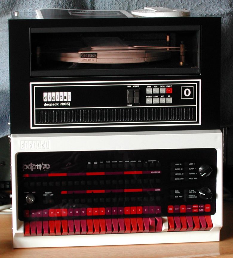
After playing for a while with the PiDP-11/70, I wanted more "look & feel" and more "the experience" of using a real
PDP-11/70 system. The choice for an add-on peripheral was quickly made, because I always liked the looks of the RK05 diks drive.
Two models of the RK05 disk drive exist(ed), the one with a fixed disk (RK05f), and the one with a removable disk (RK05j or
RK05). For both models a front panel must be designed, including the two switches and eight indicator lights. That's all for
the RK05f. But for the RK05j a working front door has to be designed, and not least an RK05 cartridge has to be made for a
complete experience of swapping the disk cartridge, just like you do on the real thing!
The major objects to realize a functional RK05 disk drive are the following.
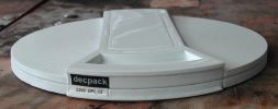
The front panel is the mounting base for the door, the switches and the indicator lights. For that reason I decided that the front panel must be made of metal, not of some sort of plastic. Looking at a real RK05 drive, you see that there are a lot of "features" on the front panel, such as lines, text, drive number, the D|I|G|IT|A|L logo, and a row of ventilation slits. As "looks" define the success of the replica, I decided to draw the front panel using Front Panel Express. The result is great, but it comes at a cost ... every item, drilled hole, engraved line, text, etc, costs ten to fifty Euro cents, and it all adds up. I already had the D|I|G|IT|A|L logo from the "pedestal PDP8i" project, otherwise this front panel would have been really expensive. On the rear side of the front panel are several M3 threaded holes which are used to mount the front door and inner box for the cartridge, and the outer box enclosure.
 |
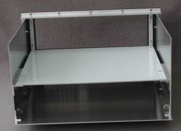 |
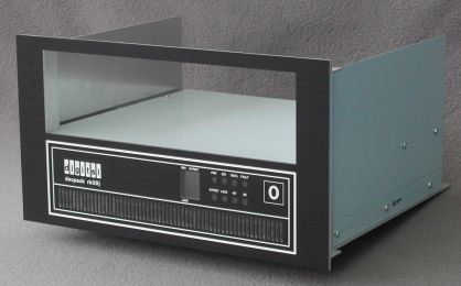
| front view of the RK05 box | rear view of the RK05 box |
The aluminum sides walls and bottom plate are attached to the front panel using "L" angled aluminum profiles. The bottom of the
cartridge "bay" is also mounted to the front panel using an "L" profile, and supported at the rear side using "L" profiles that
are mounted on the side walls.
As you can see in the rear view, two small "L" profiles are also mounted at the left and right side of the door opening. These
profiles are used to mount the cartridge "bay" left and right side walls, and have a filed "D" shape notch right behind the rear
side of the front panel. These notches are the pivot points for the front door.
On the front panel are two switches. LOAD/RUN is a standard ON/OFF switch, WT PROT is a momentary switch. The switches are mounted on a separate aluminum bracket. I used Front Panel Express to design the bracket. The aluminum bracket is mounted on the rear side of the front panel using M3 screws and stand-offs so that the switches are leveled with the front panel.
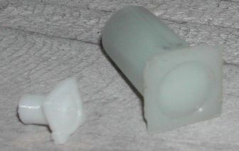 The front panel has 8 indicator lights, one red and 7 "white" lenses. In the picture at the right side is a white lens of the real
RK05 drive, and a 3D printed lens. The rear side of this lens has an inner diameter of 3 mm, so that a 3 mm LED fits snug in the
lens.
The front panel has 8 indicator lights, one red and 7 "white" lenses. In the picture at the right side is a white lens of the real
RK05 drive, and a 3D printed lens. The rear side of this lens has an inner diameter of 3 mm, so that a 3 mm LED fits snug in the
lens.
I decided to make a small PCB on which the LEDs are mounted. On this PCB is also the
interface to the PiDP-11/70 I2C connection of the Raspberry Pi. The interface uses one MCP23017 which has 16 digital I/O pins.
All 16 I/O pins are used! 7 are needed for the indicator lights (PWR is connected directly to the power supply),
2 are needed for the two front panel switches, 2 are used to define the drive number (the interface hardware supports 4 drives), 3 are
used to define the disk file container (see RK05 data cartridge), one I/O pin is used to detect whether the front door is opened or
closed, and the last I/O pin is used to control the door lock solenoid.
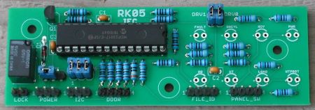
The assembly of the PCB is straight-forward.
Note that the LEDs are soldered at the rear side of the PCB!
After all components (except LEDs) are soldered, put the LEDs on the PCB at the rear side, but do *not* solder the leads!
Install the indicator lenses on the front panel (make sure that the red lens is the FAULT indicator).
Then put the front panel with the lenses on a soft cloth. Now you can install the PCB on the rear side of the front panel using stand-offs
and M3 screws of appropriate length. Push the LEDs by the leads into the rear opening of the lenses (make sure that the red LED is the
FAULT indicator).
Check that the lenses are snug against the front panel, aligned and horizontally positioned,
then use hot glue at the rear side to fix the lenses in their position. Finally, solder the leads of the 8 LEDs on the PCB.
 |
| front panel rear side with interface PCB, LEDs, lenses and switches mounted |
The construction of the front door is "easy" in principle. The door consists of two aluminum side plates (2 mm thick), three 8 mm square aluminum rods, and a piece of "smoke grey" plexiglass (3 mm thick). The side plates have a specific shape, because they are also used to limit how far the door can be opened, the stop when the door is closed (nicely parallel to the front panel), the door open/closed detection, and the door lock mechanism.
 |
| drawing of a side plate |
The solenoid needs some 15 to 18 Volts for reliable operation. As only 5 Volts and 3.3 Volts are available, a small DC/DC
step-up converter is installed. You can buy such DC/DC converters on eBay for less than 5 Euro. I found that switching the
solenoid causes spikes that influence proper functioning of the MCP23017 chip. Therefore, a snubber network is added across
the solenoid connections. The snubber network consists of a diode in series with a resistor and parallel to that resistor a
capacitor. The diode is an 1N4007, the resistor is 100 Ohms 2 Watt, and the capacitor is 100 nF.
The cartridge bay is sort of a box inside the RK05 box. This inner box is made of two aluminum side plates and a bottom plate. The side plates and the bottom plates are mounted on the frontpanel using small "L" angled aluminum profiles. The "L" profiles are positioned on the front panel in such a way that the attached side plates and bottom plate align with the opening in the front panel. A 2 mm groove is filed in the "L" profile at the lower left and right side. The M2 screws of the front door pivot in this groove, and the side plate keeps the M2 screw in place.
Underneath the cartridge "bay", attached to the bottom plate is a CNY37 slotted optical sensor. When the front door is closed the arm of the side plate moves into the slot. The signal is used for the "door open/closed" detection.
 |
| view at the bottom of cartridge bay floor |
cartridge "bay" floor
The cartridge "bay" has a bottom and a floor. The bottom is used to mount the door locking mechanism and the door
open/close detection sensor. The floor is a separate 1 mm thick aluminum plate. At the corners of the front side the floor
plate has small "L"-shaped brackets with a 2 mm drilled hole. The front door also has small "L"-shaped bracket with an
M2 screw. When the front door opens the floor plate pivots on the M2 screws and moves a little up in vertical direction.
That movement will affect the position of the floor plate at the rear side. For this reason, the floor plate rests on a
roller at the rear side.
The roller is made of an M3 threaded rod which is attached to the vertical sides of the inner box. Between the inner box
sides a round metal tube is on the M3 threaded rod.
On the floor plate are two small round metal tubes mounted using an M2 screw through the floor plate. The M2 nut is inside
the tube, just at the ends of the tube.
The RK05 cartridge is inserted into the drive and slides on the metal tubes completely into the drive until the front side
of the cartridge "bumps" against the USB connectors. The uSB connectors are mounted on a bracket. That bracket is mounted
at the rear end of the floor plate.
3 mm solid metal rod is mounted in stand-offs on the floor to guide the cartridge in the correct position and orientation,
just like in the real RK05 drive.
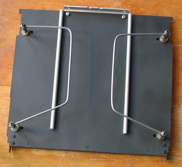 |
| floor plate with pivot points, guidance metal rods, and lower part of USB connector bracket |
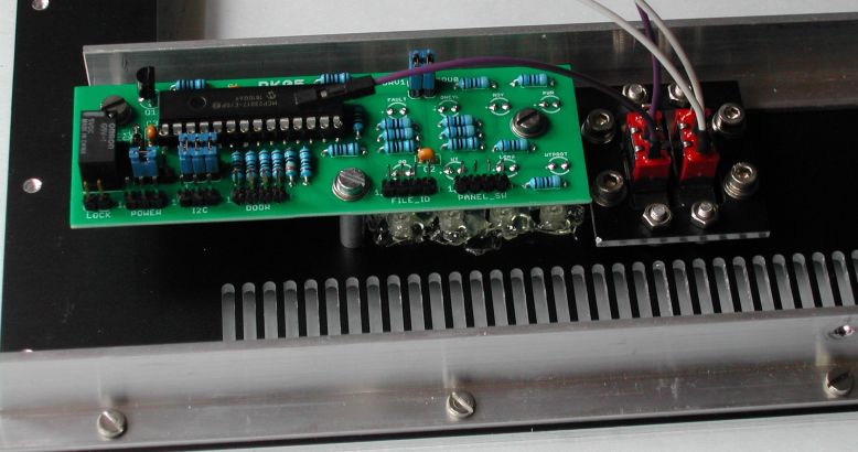
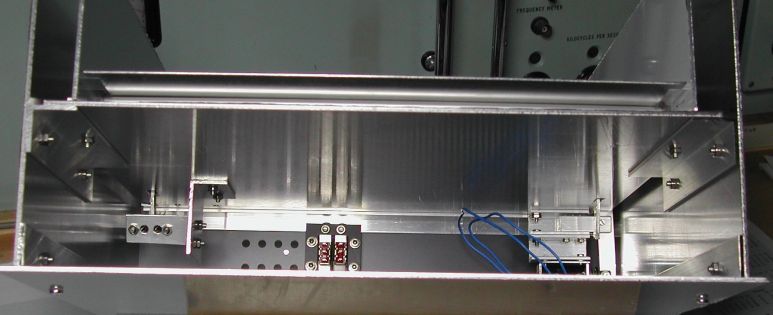
The front door lock mechanism is also mounted on the bottom plate. Note that the lock mechanism is at the right side (view from
the rear side) and the indicator lights (and PCB) are at the left side. They cannot be at the same side! The slotted sensor is
at the right side. In the picture you can see that the floor of the cartridge "bay" (bottom plate) is mounted on the "L" profile
attached to the front panel, and at the rear side with two "L" profiles on the sides of the (outer) box.
Above the floor plate you can see the roller shaft and laying on it the cartridge floor on which the cartridge slides. The
cartridge floor (1 mm thick aluminum plate) is attached to the front door. When the front door is opened the cartridge floor is
raised a little at the front side. Doing so, the floor is slightly "slanted" upward, thus making siding a cartridge into the
cartridge bay easier.
The RK05 cartridge was not easy to realize. I went to a local shop with 3D scanning equipment, but although the shape of
the cartridge *looks* to be relatively simple, it was deceivingly difficult to scan! They needed several attempts and
burned a lot of hours on the scanning of the cartridge before a satisfactory result was obtained. Many scans where good
at some curves, but were really bad at other surfaces. In the end they charged me just one hour for their service and
said that it was also for them an interesting learning.
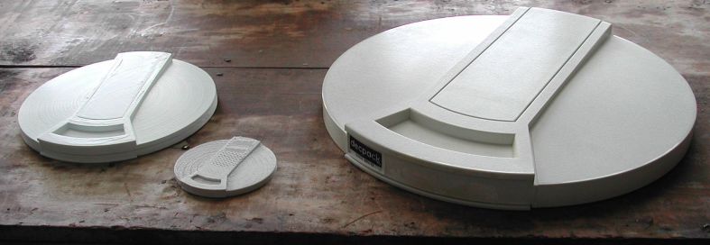
A collegue at work has a 3D printer, and he learned a few things how to print the .stl file. Don't ask for details, I
really have no knowledge at all of 3D printing. First he printed a scaled small model of the cartridge (70 mm diameter)
to see how well it would print. This small model still has amazingly much details! I joked that if we scaled the model
even more, we could make a key chain RK05 cartridge ![]() .
He split the object in two halves and scaled them so that the diameter is 210 mm. Printing of one halve takes 20 hours!
.
He split the object in two halves and scaled them so that the diameter is 210 mm. Printing of one halve takes 20 hours!
 |
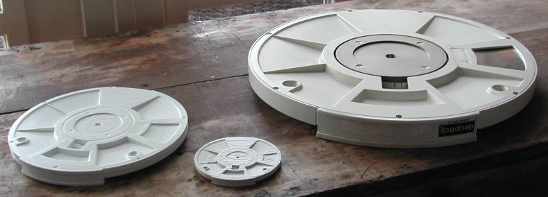 |
| 210 mm scaled cartridge model, 70 mm test sample, and original RK05 cartridge |
In the above pictures the two halves are just laid on each other. They are glued together with hobby glue.
To get a working RK05 cartridge it must be possible to write and read data to and from it. Obviously, a magnetic platter
driven by a motor and a read/write head would be way too complicated. But inside the printed model is plenty of room to hide a
USB stick. The trick is how to make a mechanism to connect the USB stick to the "outside world" when the cartridge is loaded
in the RK05 drive. More about that a bit further on ...
On the PiDP-11/70 mail list was a discussion of the scaled RK05 cartridge. It turned out to be a not-so-good idea to have
many cartridges, although that would be most realistic to how it was. Given the storage capacity of modern USB sticks, you
could easily store hundreds of RK05 cartridges on one USB stick. If you would indeed store many RK05 cartridges on one USB
stick, what's the point of making a model of the RK05 cartridge? Just glue a picture of the cartridge in the front door
"window" and be done. In my opinion, that was too way off from reality, so some compromise had to be made.
Using a second USB connection, you have four connections to the "outside world". That is good for 3 bits and a common
connection. In the cartridge is a 6-pin header on which you can put 3 jumpers. With the jumpers you can specify one of 7
container files stored on the USB stick. The eighth combination (no jumpers) is used for "no cartridge loaded" detection.
With this solution you can have 7 "virtual" RK05 cartridges in one "real" cartridge. To acess an other virtual cartridge
you have to unload the cartridge from the drive, set the jumpers and load the cartridge again. So, just like it was, you
are a "disk jockey".
 |
 |
| USB stick and 3 jumpers for container file selection | |
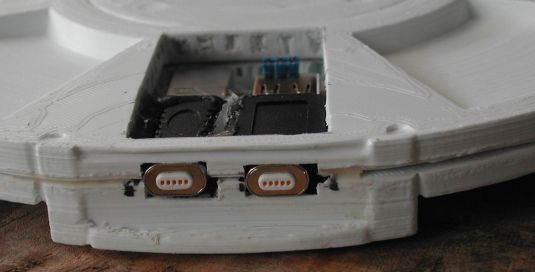
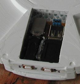
On the left side is a USB type C female to USB type C female adapter, and on the right side is a USB type C female to USB type A
male adapter. At the inside end of the adapter at the left side is a small USB "stick". male adapter. At the inside end of the
adapter at the right side is a type A female socket on a piece of perforated board. Next to that are the three jumpers. The PCB
is glued in the pocket and the left adapter is glued on the PCB.
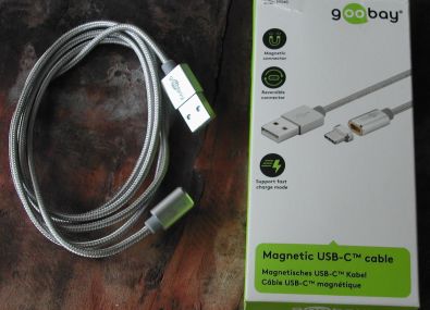
The connection to the "outside world" is realized using USB type C connectors that are magnetically coupled. The small piece is
plugged on the adapters inside the cartridge. The opposite magnetic connector is mounted in the RK05 box in a rubber ring for
some flexibility.
A standard USB connection would be difficult to make as it requires excellent alignment and you have to push the cartridge
(USB connectors) in the "outside world" USB connectors. Using the magnetic coupling the alignment of the connectors is less
critical (if one side is mounted with some free movement possibility), and the force to connect (push/pull the cartridge) is
almost none.
Software is added to SimH to make the RK05 drive work as the real thing. The software consists of 2 major parts.
The first part is the addition of a "physical" RK05 drive in SimH. The second part is the "RK05 behavior controller".
| Back to top |