RK11-C disk controller for the RK05 removable disk drive
| More Blinkenlights are always good RK11-C disk controller for the RK05 removable disk drive |
|
Wanting to add more "blinkenlights" to the PiDP-11/70, I was looking for an additional unit with lots of lights. I once saw the RK11-C controller for RK05 removable cartridge drives, and I also knew that this controller included a half-height panel with many lights to indicate the status and what the controller was doing. These indicator panels exist of four rows of 36 small lamps, and connect to a backplane with 4 "paddle" boards. Examples of controllers that had these indicator panels are the DX11 (PDP-11 peripheral to bus&tag IBM) and the RP11 controller (for "RP0x" disk drives). This type of indicator panel was also used for several PDP8 peripheral controllers, as far as I know.
I have the DX11 and the RP11 indicator panel, so these could serve well as an example, but after looking at DEC indicator panel , more specifically Digital Equipment Corporation Indicator Panels the choice for the indicator panel was easy. It would have to be the indicator panel of the RK11-C controller. That would also fit very nicely together with the RK05 removable disk cartridge drive I already made for the PiDP-11/70.
 |
So, initial drawings were created with FrontPanelExpress. The drawing you create with FrontPanelExpress is exactly what you will get, and while designing you can check
what the costs will be. It is a pity though that they do not supply "brushed black anodized aluminum", but only "black anodized aluminum". I really liked the "brushed" effect. The
front panel of the RK05 disk drive is made of "brushed black anodized aluminum", but for the RK11 controller I will have to settle for "black anodized aluminum".
The major objects to realize a "functional" RK11 controller are the following.
The front panel is drawn using FrontPanelExpress. Their website for the USA is FrontPanelExpress , their website
for Europe is FrontPanelExpress. From the website you can download the CAD software for free, and the GUI is quite
user-friendly. At least, I got quickly results and I am definitely not a CAD artist. But it takes some time to get every item placed exactly correct.
As most of the costs of the front panel is the drilling of 144 (!) holes and the associated text legends, I choose a material thickness of 4 mm. Thicker material adds to
the cost (every hole has to be drilled "more deep"). Using a thickness of 4 mm enables threaded holes at the rear side of the aluminum plate. These threaded holes
can be used to attach the PCBs with the LEDs and mount an aluminum box to the front panel, making the RK11-C controller a "unit".
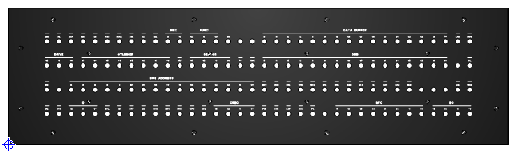 |
| view of the RK11-C front panel design |
The width of the aluminum front panel is 315 mm. That is approximately 60% of the real physical size, but it fits exactly with the PiDP-11/70 front panel (and RK05 drive). On the rear side are threaded holes to mount the two LED PCBs and small "L" angled aluminum profiles from the local DIY shop to which aluminum plates can be mounted to make a box.
The indicator panel is a "standard" part with 144 lamps. The RK11 controller uses most of them. When you look at the RK11 front panel, you see that several lamps are grouped
for example, to show the 16-bit memory address. But the same lamps may have a different meaning on an other controller that uses this "standard" indicator panel, and grouping
may be completely different, or even absent. Further, one PCB for all 144 LEDs is big.
There is no room to implement the interface hardware on the LED PCB, so the interface has to be on an other PCB.
That led to the following choices.
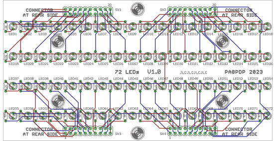 |
| Eagle design view of the component side of the 72 LEDs PCB |
The 72 LEDs and their series resistor are soldered on the component side of the PCB, the four 2x10 headers are soldered on the opposite side.
The LED PCBs are mounted onto the front panel with four M2.5 screws and stand-offs, and fit next to each other to form a 144 LEDs panel. The distance between two LEDs is
0.3", and the distance between two rows is 0.6".
You can solder the resistors now, but do not solder the LEDs. I used the wrong part from the Eagle library for the resistors. The resisotrs on the LED PCB have
a pitch of 0.2 inch. "Normal" resistors have a picth of 0.3 inch, so the standard size resistor will not mount nicely on the PCB. Sorry for that, my mistake. Just bend
the leads of the resistor 90 degrees, put it on the PCB and solder one lead of the resistor flush on the PCB, and the other lead "pulled" to the PCB. That does not look
great, but when the PCB is mounted against the rear side of the front panel, nobody will see my goof-up.
After soldering the resistors, mount the four 2x10 (male) pin headers on the rear side of the PCB, and solder them at the component side.
The interface hardware consists also of two PCBs, but they are not identical. Each interface PCB contains five MCP23S17 2x8bit I/O expander ICs, in total supporting 80 I/O connections. 72 are used for the LEDs, the remaining 8 outputs are available for "other use". The lay-out of the traces is such that a "groups", for example "DRIVE", "CYLINDER" and "SECTOR" on the "left" PCB, and "DATA BUFFER" and "DSB" on the "right" PCB are hardware-wise (and thus also software-wise) connected to an 8-bit port. This makes the interface software easier, no "bit shuffling" is needed. It also reduces the number of output actions.
 |
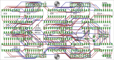 |
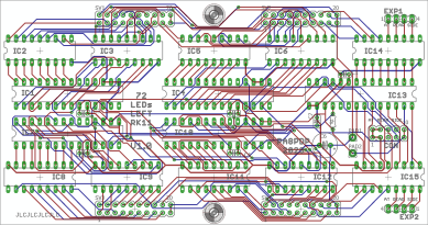
| Eagle design view of the left side interface PCB | Eagle design view of the right side of the interface PCB |
As up to 16 LEDs all connected to a single MCP23S17 might be on, the interface PCB also contains driver ICs enabling the total current needed for all LEDs. The MCP23S17
can sink 150 mA, or source 125 mA max. That limits the LED current for a worst case condition (all 16 LEDs on) to sink max 9 mA, or source max 7.5 mA per LED.
The interface PCBs are piggy-back mounted onto the LED PCBs, secured by two M2.5 screws and stand-offs. The four 2x10 (female) headers are soldered on the component side.
Only the interface connection CON (2x5 pin header) is soldered on the opposite side. This connector is the interface to (for example) an Arduino Nano or a Teensy. SO
(Serial Out) of the SPI interface, Chip Select, GND and +Vlogic are on these pins. As the LEDs are connected "common anode" via a driver, you can have a different (higher)
power supply voltage for the LEDs. The +Vled is connected to a pad on the interface PCB, for separate LED power supply. Next to this pad is an other pad which connects
to the +Vlogic. By connecting the two pads, the LEDs are powered by +Vlogic via the connector CON.
I thought this would be an easy, straight-forward assembly, but that was a mistake ... Aluminum "L"-profiles are mounted onto the rear side of the panel using the threaded
holes. The side walls, bottom and top of the housing box are mounted onto these "L"-profiles. As everything is scaled to 60%, I found out that everything is quite tight,
and it all fits just. That was not foreseen, so I am lucky that it does fit.
However, assembly requires a specific order, else you run into trouble later on.
The "L"-profiles are made of 2 mm thick aluminum, one leg is 10 mm, the other leg is 30 mm. The 3 mm holes in the 10 mm leg are drilled 4 mm from the edge. I drilled the
holes 3.2 mm for tolerances. The top and bottom "L"-profile fit "inside" the left and right side "L"-profile. That way, the top (and bottom) cover can be over the edges of
the side walls, looking nice. Note that the "L"-profiles for the top cover have press-fit nuts. It will be impossible to hold a nut on the inside and mount the screw that
scecures the top cover!
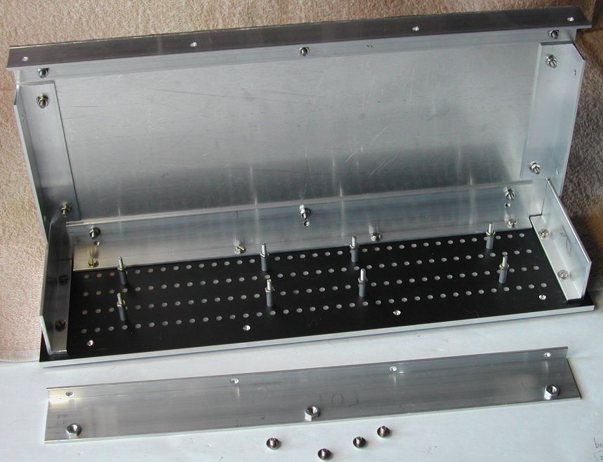 |
| "L"-profiles mounted onto the rear side of the front panel (and checking that the bottom fits too) |
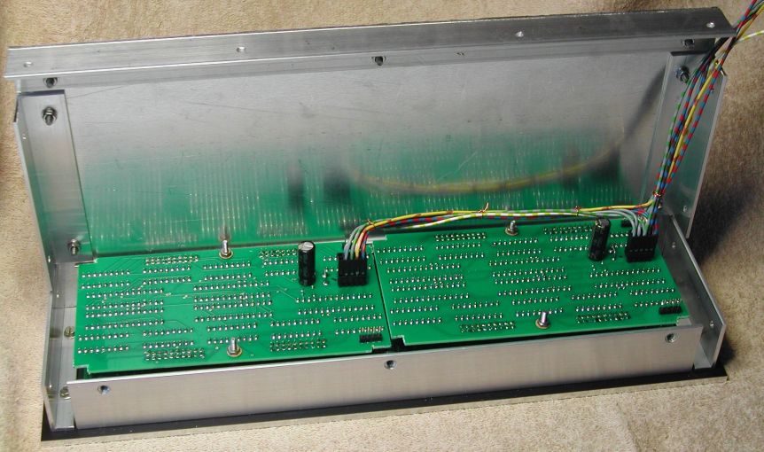
In the picture, you can see that the four M2.5 screws for each LED PCB are already mounted on the rear side of the front panel. Initially, I thought to use screws, but you have to mount the LED PCBs with the LEDs, without the LEDs being soldered first, and then solder the LEDs. That order allows you to have all LEDs mounted at the same depth into the frontpanel. Looks is everything! So, you have to put all the LEDs on the PCB (correct orientation anode/cathode, not soldering them), mount the PCBs on the front panel, and then check that all LEDs are in the front panel holes at the same depth. It is easier to mount the LED PCBs with a nut on the M2.5 screws (without a screw head) than M2.5 screws with screw head.
The LED PCBs just fit between the bottom and top "L"-profile. That implies that you have to mount the "L"-profiles onto the front panel before you mount the LED PCBs,
because the M3x4 mounting screws are not accessible when the LED PCBs are mounted! So, the holes to mount the box bottom, top and side plates must also already be drilled.
Also, before you start soldering the LEDs, make sure that you mounted the two M2.5 (length 30..40 mm) screws on each LED PCB (in the middle along the long side of the PCB).
These two screws keep the piggy-back mounted hardware interface PCBs secured, nor relying on the four 2x10 connectors. Check that LED1 on the left side LED PCB is located
above panel light ERR, and that LED1 on the right side LED PCB is located above panel light DATA BUFFER 15. If not, rotate the
LED PCB 180 degrees!
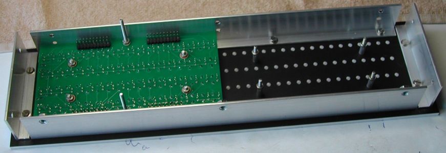 |
| Left LED PCB mounted. LEDs positioned, ready to be soldered |
Put the LED PCB with the LEDs onto the M2.5 mounting posts and verify that all LEDs protrude the corresponding hole in the front panel. If all LEDs are in the hole, lay down
the front panel on a clean table (to avoid scratching the front), and mount the LED PCBs each with four M2.5 nuts. Test that the lens of every LED is resting on the table
surface. Then solder one lead of the LED. Repeat this for all 144 LEDs! After that job, you can look at the front and inspect that all LEDs are identically mounted in the
holes. If not, you can apply a correction. When all LEDs are mounted identically, you can solder the other lead of all LEDs.
The visually important assembly is now done.
Soldering the interface boards is straight-forward. I always use top-quality IC sockets (machined pins). If an IC goes defective, replacement is simple. Machined pin IC
sockets are not cheapbut reliable, you can also use double-spring sockets. Do not use single spring sockets, those are rubbish. Note that the orientation of the ICs is not
identical for all of them! Also note that the 1x4 pin EXP1 and EXP2, and the 2x5 pin male CON are mounted on the solder side and soldered on the component side. Do not (yet)
solder the four 2x10 female headers on each interface board.
Solder the small 100 nF decoupling capacitors, and the resistor. Put the large polarized capacitor on the solder side and solder the leads on the component side. Observe
correct polarity!
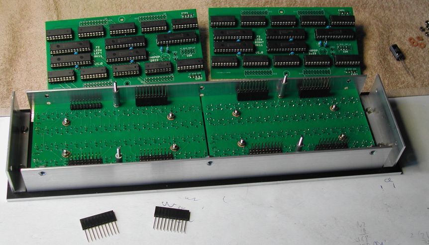 |
| LED PCBs mounted, female headers with long solder pins for the interface boards |
Place the female headers with long (11 mm) leads on the 2x10 male headers of the LED PCBs. I used 10-pin single-in-line headers, simply because the local had those available. 2x10-pin double-row headers might make the fitting of the interface board a bit easier. Put the stand-offs on the M2.5 screws on the LED PCBs. Mount the interface boards with a bit of wiggling, until all female header leads protrude through the header holes of the interface boards. Secure each interface board with the two M2.5 nuts. As the interface boards are basically fixed using two screws in the middle of the board, check that all header pins protrude at both sides of the board, and then tighten the two nuts for each board. Finally, solder the pins of the female headers.
 |
| Interface boards installed and wired |
The MCP23S17 IC uses SPI for its (bi-)directional communication, and the address is hex 2x (where x can be between 0 and 7). As the total design uses 10 of these devices,
each interface PCB (with its five MCP23S17 ICs) includes a "Chip Select" signal. Both interface PCBs use addresses (hex) 20 .. 24, so the CS for both interface PCBs must be
mutually exclusive. The RK11-C interface needs an interface to receive LED commands. Using an Arduino Nano or a Teensy (higher performance, if needed), the interface PCBs
connect using the USB connection. The USB connection creates a virtual COM port.
The CON header on each interface board has pins for (logic) power supply and GND, the SPI interface signals clock and data, and a "Chip Select" input.
| CON pin | Function | Remark | Nano pin |
Power supply SPI connections Board Chip Select |
| 1 | GND | GND | ||
| 2 | GND | GND | ||
| 3 | GND | GND | ||
| 4 | GND | GND | ||
| 5 | n.c. | no connection | ||
| 6 | SCK | SPI clock | ++ | |
| 7 | SI | SPI data in | ++ | |
| 8 | CS | board Chip Select | ++ | |
| 9 | +5V | logic power | +5V | |
| 10 | +5V | logic power | +5V |
Some form of command protocol has to be designed. I had two options. Either some form of command to set/reset the state of a single LED, or some form of command to set/reset an interface port. Using a command that allows to change a single LED is straight-forward, and works perfectly fine for "items" that are just one LED, like error or status bits. However, for "items" that are a group of LEDs, for example the 8 LEDs of the CYLINDER group, the "single LED" approach is is a bit awkward. Furthermore, this approach is also performance-wise very bad, because the update of the CYLINDER group would require 8 commands to be sent. Okay, by maintaining a local copy of the state of the LEDs you can avoid a needless update of one LED (because it state is not changed), but worst case it will require 8 commands.
In order to minimize communication between SIMH and the RK11 interface, the interface hardware is such that a logical "group" of LEDs (such as CYLINDER) are also in hardware a group, where a group is 8 bits, one byte. The LEDs of a smaller "group", like DRIVE and SECTOR, are always contained in one byte. Using the "knowledge" of how the interface hardware is realized, it is logical to have commands that also operate at the "byte-level". So, the command must somehow indicate to which 8-bit output port the 8-bit data has to be sent.
The following command scheme is implemented in the Arduino Nano.
| Command letter | ||||||||
|---|---|---|---|---|---|---|---|---|
| 7 | 6 | 5 | 4 | 3 | 2 | 1 | 0 | |
| L | ERR | HE | SCP | MNT | IAI | FMT | RWA | SSE |
| M | CR | IDE | MEX 01 00 |
FUNC 02 01 00 |
GO | |||
| l | CYLINDER 07 06 05 04 03 02 01 00 | |||||||
| m | DRIVE 02 01 00 |
SRF | SECTOR 03 02 01 00 | |||||
| N | BM | IRQ | WCO | ID 02 01 00 |
DPL | |||
| O | HD | DRU | SIN | SOK | DRY | RWS | WPS | SEQ |
| P | EXP# | EXP# | EXP# | EXP# | CSEC 03 02 01 00 | |||
| n | BUS ADDRESS 15 14 13 12 11 10 09 08 | |||||||
| o | BUS ADDRESS 07 06 05 04 03 02 01 00 | |||||||
| p | PO | HOK | EXP# | EXP# | EXP# | EXP# | ||
| R | DATA BUFFER 15 14 13 12 11 10 09 08 | |||||||
| S | DATA BUFFER 07 06 05 04 03 02 01 00 | |||||||
| r | DSB 15 14 13 12 11 10 09 08 | |||||||
| s | DSB 07 06 05 04 03 02 01 00 | |||||||
| T | PRE | HDR | DAT | CHK | PA | DLT | TE | |
| U | IWC 07 06 05 04 03 02 01 00 | |||||||
| t | WTG | ROH | DRE | OVR | WLO | SKE | PGE | NXM |
| u | NXD | NXC | NXS | CSE | WCE | |||
| V | EXP# | EXP# | EXP# | EXP# | BC 03 02 01 00 | |||
| v | LWD | RDG | IDL | EXP# | EXP# | EXP# | EXP# | |
The Arduino firmware maintains a local "shadow" copy of the state of all the LEDs. When the received command results in no change of the data of the specified port, the
actual output command via SPI to the MCP23S17 IC is not executed. This eliminates the output cycle, thus making the processing of a stream of commands faster. The firmware
has a buffer for 100 commands, and the only task of the firmware (besides receiving commands) is to execute all commands as fast as possible. If the command reception queue
is full, due to a fast sequence of sending commands, those commands are simply lost. As soon as there is room in the queue, a received command is stored in the queue, and will
be executed.
The Arduino Nano firmware ("sketch") can be downloaded from here:
rk11-ctrl.zip.
When the zip file is unzipped in a folder, that folder contains a folder named "rk11-ctrl", and in that folder is the file "rk11-ctrl.ino". Assuming that you have the
Arduino IDE installed, you connect the Arduino Nano to the PC, and double-click the "rk11-ctrl.ino" file. The Arduino IDE starts and the sketch is loaded. First, you
set in the IDE the "target" (Arduino Nano) and the bootloader, and the COM port to which the Arduino Nano is connected. Then you compile the sketch. If all goes OK,
the sketch is uploaded to the Arduino Nano.
To test the RK11 interface hardware and firmware, an application is written in Python. Python is a language in which you can relatively easy create a graphical user interface. With little effort I created a graphical representation of the RK11 front panel. With the mouse you can point to an LED and when you "click", the state of the LED changes from a grey appearance to white (switching on), or from white to grey (switching off), and the appropriate command is sent to a serial port.
The test application has two tabs. On the first tab (which appears when starting the app), you can select the virtual COM port which is created when the RK11 front panel USB cable is plugged in. The "flashing" exclamation sign disappears as soon as a COM port is selected from the drop-down list. The button below the selection box hows the state of the COM port. Initially the port is closed. By clicking the button the serial communication port is opened.
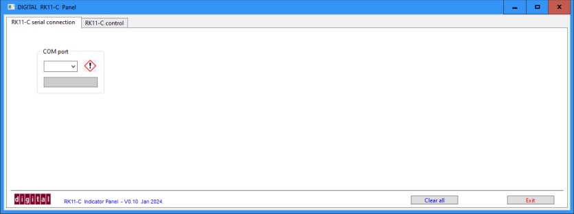 |
| Python test application - tab 1 - virtual COM port selection |
The second tab contains the graphical representation of the RK11 front panel.
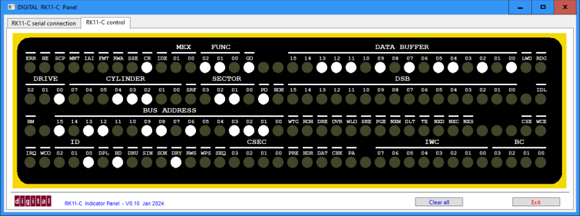 |
| Python test application - tab 2 - some LEDs on |
The Python test application consists of the Python program and 5 GIF images (DIGITAL logo, exclamation "error", "LED off",
and "LED on" in white and in red appearance. A simple change in the Python program sets the "on" color of the LEDs.
The Python test application can be downloaded from here: rk11-testapp.zip.
Unzip the file to any folder (resulting in the mentioned 6 files).
To run the Python program you (obviously) need to have Python installed on your PC (I am using Python 3.9.5). Further, the application requires the
WxPython and PySerial package. When you have the Python program installed, the following two commands, issued in a CMD window, install the two packages.
|
The RK11 front panel is connected to the Raspberry Pi using a USB port. I am assuming that you are using a PiDP-11/70.
Thus, to send commands to the RK11 interface, the proper serial port (USB) must be configured in SIMH.
Note that this serial port does not have a "serial port" in the simulated PDP-11 environment.
Before you start SIMH, you physically connect the RK11 interface with a USB cable to the Raspberry Pi, and check which serial interface is made available,
for example "/dev/tty0". Then you can start SIMH.
In SIMH you "connect" the RK11 interface with the new (SIMH) command "RK11=/dev/tty0".
That's all!
Obviously, the SIMH version has no knowledge of the RK11 interface. Just like the implementation of the RK05 disk drive, several SIMH files need some modifications. First, the command to connect to the virtual COM port must be made available, and then data and state functions of the RK05 device must be changed, so that information is sent to the RK11 interface. Here is a short list (in sequence) of tasks that have to be implemented.
| Back to top |