DUAL DIVERSITY SWITCHING UNIT
|
MA.168 / MA.168B DUAL DIVERSITY SWITCHING UNIT |
|
|
|
|
|
| HIGHLIGHTS |
|
|
|
|
The Dual Diversity Switching Unit accepts M.C.W. or C.W. signals of telegraph speeds up to 1000 Bauds.
R.T. or single sideband working is selected by a switch.
The unit is designed for use in conjunction with any two of the RACAL Communications Receivers in the RA.17 or
RA.117 range. If the RA.17A receiver is used, a minor modification is required.
The unit has a built-in power supply.
The figure shows the block diagram and interconnections of the equipment to which this brief description refers.
The 100 kc/s i.f. outputs from each receiver (A and B) are applied to the two inputs of the Diversity Switching Unit.
Each signal path contains an amplifier and detector circuit, the output of both detectors being fed to a D.C. adder
and monitor circuit.
The polarity of the output from the circuit is a function of the relative amplitudes of the i.f.
signals A and B, and is used to operate two on/off gates (A and B) in the i.f. transimission paths. One polarity
causes gate A to open; the other causes gate B to open. At all times the gate in the path of the stronger signal is
held open thus giving an unattenuated output derived from the stronger i.f. signal. The figure shows the connections
for two RA.17A Mk.2 or RA.17L receivers. Click
here
to see the connection diagram for two RA.117 receivers.
The output from the two i.f. gates is taken to a common point from which it is distributed on three lines.
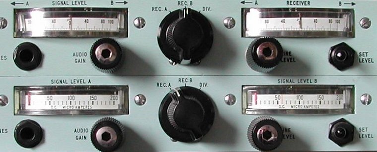
The i.f. input signals to each path are continuously monitored by two meters.
One of these meters can also be used to monitor the line output level.
Indication of which path is in use is provided by two miniature cathode ray indicators.
Power for all circuits is derived from a stabilized power supply contained within the unit.
If you have ever listened to short wave or medium wave especially in the evening hours, you know that the received
signal varies in strength. One of the causes is that the aerial receives signals from all directions. That means
that the signal you tuned the receiver to can come in from a direct path (transmitting station to your aerial), but also
from a reflected path (transmitting station via a reflection for example a building to your aerial). Another path
can be also a direct path, but from the opposite side; that path often produces a weaker signal strength.
All these signals from the same transmitting station are added to one input signal to your receiver. As with
all signal additions, sometimes the signals are in phase and they amplify each other, sometimes the signals are in
opposite phase (180") and they cancel each other. Of course, the phase between the signal varies between 0" and
180". This effect is called fading and produces a signal that grows stronger and then diminishes again.
 Diversity reception is a technique that tries to cancel out the effects of fading.
Several method exists for diversity reception. The RACAL MA.168 Diversity Switching Unit uses two receivers
with identical characteristics, and each receiver has its own aerial. The two aerials are physically spaced from
each other, or installed at an 90" angle relative to each other.
Both receivers are obviously tuned to the same frequency, and both receiver outputs contain the fading effect.
However, because the aerials are oriented differently, it is not likely that both receivers have the same amount
of fading at the same time.
Diversity reception involves the automatic selection of the output of the receiver that has the strongest signal.
With this RACAL equipment, not all RACAL adept listeners can make room to set up for diversity reception. After
all, you need two receivers (RA17A Mk.2 or RA.117), probably you have a Preselection and Protection Unit MA.197B
so you need two of these as well. For long wave reception (10 kc/s to 1 Mc/s) two additional (RA.37 / RA.137 or RA.237)
are needed. Finally, you need the space outside to install two more or less identical aerial systems with
a sufficient large space between them or perpendical to each other.
For most amateur listening stations these are not simple requirements. If you have the space and the room in your
home, you will be amazed what a difference diversity reception sometimes can achieve!
The adaptor is designed for rack mounting or for fitting in a suitable cabinet.
All electrical connections with the exception of the headphones are made at the rear side of the unit.
A dust cover is fitted which provides protection from dust and dirt.
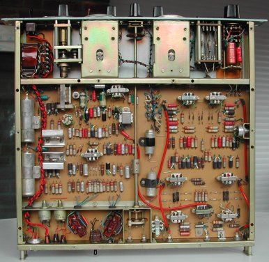
First of all, let me say that I do not have any documentation of the MA.168.
These are my quick findings by simply comparing the front and the rear side of both units.
The rear side is easy as there are no differences, that is when looking at the rear side, both units have the
same items.
From left to right they are the following: