| MAINTENANCE Board Set | KM11 |
The KM11 consists of two small single-height modules.
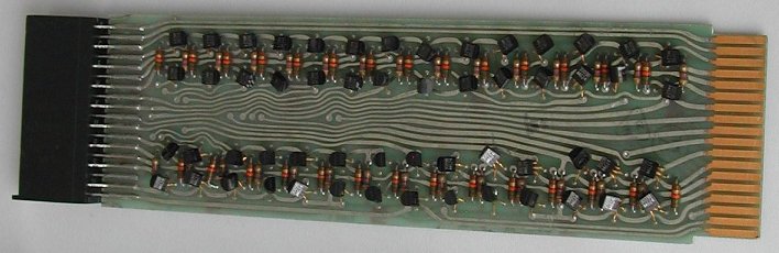
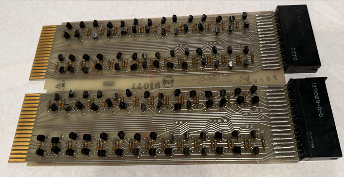
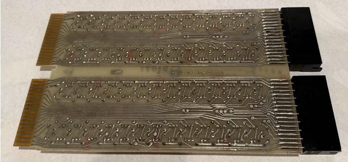
The W130 is plugged into the backplane (position B02) and has several buffer circuits. This board buffers interface signals of the following PDP-11 processors: PDP-11/05, PDP-11/10, PDP-11/35, PDP-11/40, and PDP-11/45, The module can also be plugged in the following device controllers: RK11-C and RK11-D (RK05) disk controllers, the RX01 floppy drive, and maybe a few other devices too.
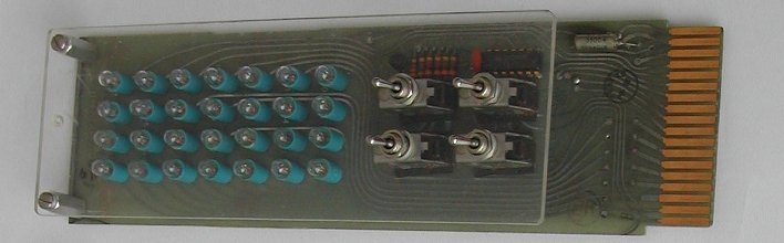
The W131 has 28 lamps (real filament bulbs) and four miniature switches. This module is placed in the header on top of the W130. A foil was put on the plastic cover over the light bulbs with text printed indicating the signals that were connected to each lamp.
From Mike Thompson I received the following pictures; never seen before! He says that during the restoration of a PDP-11/40, he found the W133 in his collection. Having two KM11s with light bulbs, he can watch the microcode stepping of the CPU and at the same time the microcode stepping of the EIS and FIS options. Using the W133 makes the KM11 more stable in the backplane as well.