| Small-housed VAX | MicroVAX3300 |
The MicroVAX3300 is housed in a BA215 box. This box is not as wide as the BA213 and BA440 housing, but it has all the typical properties. On the right side of the front is an up/down sliding window which can have 3 positions. These positions can be locked out or made accessible by the key on the left side of the front.
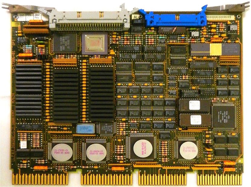
Standing in front of the BA215 with removed front cover, you see from left to right a "blind" metal panel, 6 slots, and the power supply. In the BA213 box, instead of the blind metal panel is a second power supply installed to accommodate slots #7 to #12. The right-most slot is slot #1. Slot #1 (thus at the right side of the card cage) holds the VAX CPU module M7624, which can be a KA640-AA or a KA640-BA. The KA640-AA is the MicroVAX 3300 CPU running multi-user software, the KA640-BA is the VAXserver 3300 CPU running single-user software. Slot #2 holds the first 8 MB memory module M7621-A, MS650-AA. As you always need the CPU and the first memory module these two slots have one common cover panel with two labels (KA640 and MS650). Slots #3 to #6 are available for additional memory modules (2 maximum) or other options such as serial interfaces, printer and interfaces, etc.
The MicroVAX 3300 is also named "Mayfair II", supports QBUS and the DSSI (DIGITAL Small Storage Interconnect) disk interface.
The KA640 uses the CVAX chip (100 ns microcycle) with 1 KB cache on chip, and 4 MB (32 bits data and 7 bits ECC) of RAM storage
on the module. The maximum supported amount of RAM storage is 28 MB (with ECC), being 4 MB on the KA640 itself and up to three
MS650 modules (each 8 MB), if enough Q22/CD slots are available.
The performance of a VAX is often indicated by comparison to the first VAX model, the VAX-11/780. The performance of the
VAX-11/780 is 1 "VUP", VAX Unit of Performance. Using this comparison, the KA640 used in the MicroVAX 3300 has a rating of 2.4 VUP.
The BA215 has a 6 slot backplane. The first slot (the most-right one) is for the KA640. The next 3 slots can be used for memory
modules. The backplane has the Q22 bus in the AB rows of slots 1 thru 6. The CD interconnect is in the CD rows of all 6 slots.
The BA215 has one power supply (at the right side of the processor) which can deliver 7.0A (max) at +12V DC and 33.0A (max) at
+5V DC. The maximum current at +12V and +5V must be below 230 W.
In this microVAX 3300 only slot 2 has a memory module, slot 3 is empty. In slot 4 is an M7559 which is the TK70 interface. Slot 4
has an CXA16 - M3118, 16-line asynchronous multiplexer, which gives the system 16 serial communication lines to connect terminals.
Slot 5 and 6 are empty.
The system console is directly connected to the processor. It uses a DEC-423 modular plug, also known as "MMJ" (Modified Modular Jack). It looks like a standard RJ45 plug, but the "locking lip" is not in the center but offset from the center.
If you want
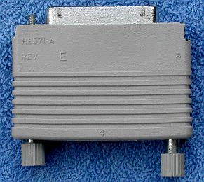
to connect the system monitor you need the connection cable (which has MMJs at both ends) and an H8571-A. The H8571-A accepts
at one side the MMJ plug and has at the other side a 25-pin fimale sub-D connector which plugs into a standard terminal.
I connected a VT510 with amber screen to this microVAX 3300.
After connecting the system console, a VT510, and a power cable, it is time to flip the power switch on the front. I thought
that the console would tell me what I wanted to know about this system without further disassembly.
The first thing I noticed after flipping the switch to ON is that the READY LEDs
of the disk drives did not turn on. Ah well, ... maybe those LEDs turn on later.
 |
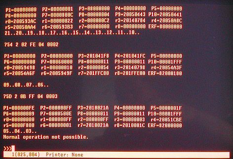 |
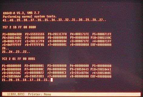
| Console output - system start | Console output - continued |
|---|
Not looking good, time to start reading the "KA640 CPU System Maintenance" manual (EK-179AA-MG-001).
The error is printed in a five-line display. The first line has six fields.
Trying to match the diagnostic printout on the console with messages described in chapter 4 of the CPU System Maintenance manual, I think I recognize ?57 seesm to point to "SII_memory", ?C2 implies something with "SCC RAM ALL", ?54 is about "Virtual Mode", and ?54 has to do with "SII target". Not very meaningful at this point. With a bit of reading I now know that "SCC" is an abbreviation of "System Support Chip", and "SII" is one of the chips on the CPU that implements the DSSI bus. DSSI stands for D|I|G|I|T|A|L Small Storage Interconnect. The other chips are DXX and four 32Kx8 static RAM chips. So, I guess that "SII_memory" is DSSI related. I have not yet removed the cover at the top next to the TK70 tape drive, but I suspect that there are no (RF30) disk drives mounted ...
| Back to top |