| ALTERNATE GEAR HANDLE
a "simple" mechanical project with 2 small switches |
 |
Introduction
Although the heading says that it is a "simple" project, nothing in pit building is as simple as it may seem at first look.
I must admit that I had a very good start by getting an original ALT GEAR grip from "Dunk, Kneeling Warrior" on
Viperpits. But as soon as I started working on the realization of the Alternate Gear handle the questions popped up. I had
seen pictures of the Alt Gear handle with the white push button in the center of the grip, but how does it all work? What is
the function of that little white button, is it needed to unlock the handle? How far is the Alt Gear handle pulled? Is the
handle spring-loaded, so it will revert automatically back to its initial position?
Operation of the Alt Gear handle
Asking on Viperpit often gives good anwers, and again, the best information came from "KK".
He quotes the information directly taken from the F-16 Manual ("T.O. 1F-16A-1"), on page 107, which I simply repeat here.
- Quote:
-
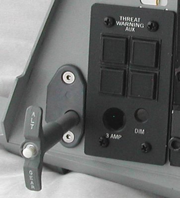
The ALT GEAR handle, located just outboard of and below the Landin Gear control panel, is used to extend the Landing Gear if
normal extension is not possible. Pulling the ALT GEAR handle supplies pneumatic pressure to open all Landing Gear doors,
extend the Nose Landing Gear, and shut off the Landing Gear selector hydraulic valve. The Landing Gear/hook emergency pneumatic
bottle is also used to lower the hook and contains sufficient pneumatic pressure for one Landing Gear extension and to hold the
hook down. The bottle cannot be recharged in flight. Since pneumatic pressure is reduced by expansion as the actuators extend,
less than the normal extending force is available. A Landing Gear reset button, located on the ALT GEAR handle, provides a means
of retracting the Landing Gear after an alternate extension if system B hydraulic pressure is available.
So, there you have it. You can pull the Alt Gear handle at any time, and the handle does not automatically return to its initial
position. You simply have to push it back yourself. Pulling the Alt Gear handle is of course only wise if the normal Landing
Gear handle fails, and your air speed is sufficiently low ... There is no locking mechanism on the Alt Gear handle, not when
you pull the handle, neither when you want to push back the handle.
The little button in the center of the Alt Gear handle is a "reset" button to retract the Landing Gear ... better not push that
button when you have "WOW" (Weight on Wheels), when you have landed!
I hope to get an answer on how far the Alt Gear handle can actually be pulled.
Construction of the Alt Gear mechanism
Basically, the Alt Gear mechanism is a handle fitted on a rod. The rod must be hollow, because the wires of the little white
button must go through it. The rod must be guided by using a tube or something else, so that the handle can be pulled without
much axial play. A small switch (or micro-switch) is used to detect the pulled-out position of the Alt Gear handle.
... simple ...
The first problem is the fitting of the hollow rod onto the real handle. After visiting a few hardware shops, I found out
that the threading inside the Alt Gear handle is 3/8 UNF.
I even found a shop where they could order a 3/8 UNF die, but it
would cost almost 34 Euro. That's a bit too expensive for cutting just one thread. However, they also had bolts with 3/8 UNF
threading (great shop!). For 3,30 Euro I got myself one 50 mm long bolt with 3/8 UNF threading. But there already popped
up the next problem. The bolt is made of steel ... I would have to drill through it radially, because two wires had to go though
it! Hmmm, deal with that later ...
From Reichelt I got a small white push button. The housing of the button fits perfect in the center opening of the Alt Gear
handle, and from another switch I "canibalized" a round locking screw ring which was just slightly too large. With a file I
carefully made the screw ring clamp-fitting in the top opening of the Alt Gear handle. I used a simple 5 mm LED clip ring to
mount the screw ring at the outer end of the threading of the push button. It looks great, but I decided to spray paint the screw
ring with the same grey paint that I used for the Landing Gear lever. That tone of grey is lighter than the dark-ish grey of the
Alt Gear handle, but it will sure look better than shiny chromium.
All I need now is something to guide the "rod" and give it some "feel". You must of course feel some friction to pull the handle.
At first I wanted to replicate the real mechanism. That is a block of metal with a tube. The block of metal is mounted on the rear
side of the Left AUX Console. The tube has a slit. Guidance pins on the rod slide through the slit so that the Alt Gear handle
can not rotate on its axis. The problem with my limited mechanical skills is how the tube will be attached to the block of metal.
So, I have build this with a block of "plastic" (actually, the correct name for the material is POM). This is how I constructed it.
- Saw the block to the dimensions so it fits behind the Left AUX Console, at the left of the THREAT WARNING
AUX console push buttons.
The block will be mounted against the rear side using the two screws of the Alt Gear
handle plate. The depth of the POM block (measured from the Left AUX Console) must be long enough to give sufficient support to
the "rod" of the handle to minimize axial play.
- Drill a hole just fitting for the rod of the handle. For my 3/8 UNF bolt, I drilled a hole of 9 mm diameter and then used a
file to make the hole just large enough. A drill of 10 mm was a little too large.
- Hold the POM block against the Left AUX Console, align the rod opening and mark the position for the two mounting screws.
Drill the holes for the mounting screws.
Now comes the (postponed) hard part. Preparing the steel bolt for its purpose.
As said, you must make the steel bolt hollow for the wires. When that is done, proceed.
Forget the steel bolt. Unless you have a lathe, good drill and patience, you will not succeed making
the bolt hollow.
After some searching I found a shop that sells aluminium rod, diameter 10 mm. It is already hollow, and material thickness is 3 mm.
That thickness is important ... I filed the last 10 mm of the end of the aluminum tube to 9.5 mm diameter. From RS I got an HSS
steel die 3/8 UNF die (part number 668-0740) for some 10 Euro, which is acceptable. (I had to buy the die stock #444-895 too, grrr).
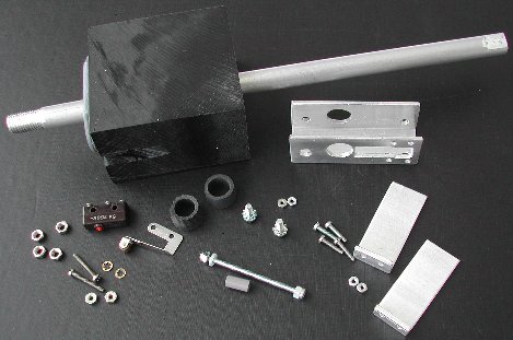
I managed to cut a nice 3/8 UNF thread on the aluminum tube, and the Alt Gear handle fitted like a glove! You can see the aluminum
tube in the picture in the POM block, it still needs to be saw to the final length.
The last part to make is the guidance so that the Alt Gear handle can not be rotated. This guidance is just a pin through the
aluminum tube and held between two plates. The pin will also activate a micro-switch when the Alt Gear handle is fully pulled.
- I used a piece of "U-shaped" aluminum profile. First I drilled two holes slightly larger than 10 mm so that the aluminum
tube of the Alt Gear handle can move freely through the holes.
- Drill two 3 mm holes in the "U-shaped" aluminum profile. Hold the "U-shaped" aluminum profile on the POM block, mark the
holes and then cut a thread M3 in the POM block so that the "U-shaped" aluminum profile can be mounted on the POM block.
- Determine the position of the micro-switch. I had to file an opening for the entire arm of the micro-switch.
The micro-switch is mounted with two M2 screws. Two M3 nuts on each M2 screw is used as a spacer so that the arm of the
micro-switch is in the middle of the shaft of the Alt Gear handle (left lower corner in the picture).
- Then I made two small aluminum "L-shaped" profiles. They just fit on the "U-shaped" aluminum profile with two M2 screws.
The space between the two "L-shaped" profiles is a little bigger than the "guidance pin" and will guide the shaft of the Alt
Gear handle, preventing axial rotation (right lower corner in the picture).
- Two rubber rings with an inner diamater of 10 mm nicely fitted between the two "legs" of the "U-shaped" aluminum profile.
They give the Alt Gear handle friction, and make the pulling and pushing more "realistic".
- Finally, mount the block of POM on the Left AUX Console and put everything together, with the Alt Gear handle tightly mounted
on the aluminum tube. Now you can determine the hole through the tube. A piece of threaded M2.5 rod is mounted. This long M2.5 rod
is guided between the two L-shaped plates, and when the handle is fully pulled it will activate the micro-switch. So the hole in
the tube is determined when the Alt Gear handle is fully pulled. Note that the M2.5 screw must also be between the two
L-shaped plates when the Alt Gear handle is fully pushed in!
|
|
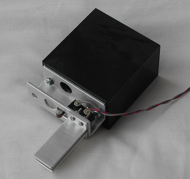
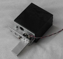
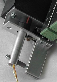
| POM block with the aluminum guidance parts |
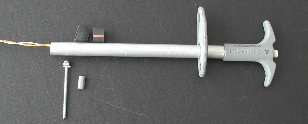
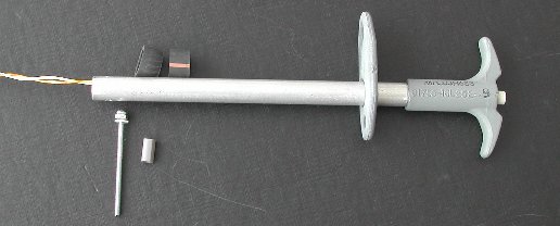
Alt Gear handle with push-button, aluminum tube, pin and friction rubber rings |
On these pictures you can see the pin through the hollow aluminum tube. The pin is a piece of M2.5 threaded rod. At the end is a
self-locking screw, at the other side of the tube is a nylon spacer with an inner diameter of 2 mm. It fastens neatly on the
M2.5 threaded rod. This spacer also activates the micro-switch when the Alt Gear handle is fully pulled out. The other
pictures show the Alt Gear handle in its normal position, and when the Alt Gear handle is pulled.
|
|
|
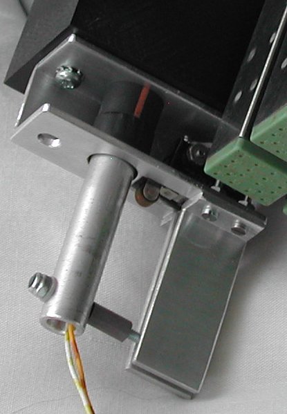
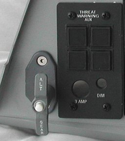
| detail picture of pin |
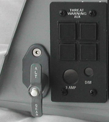
Alt Gear handle (normal position) |
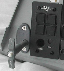
Alt Gear handle (pulled out) |