Rotary switch ... but with a "twist"
| AUDIO1 Volume control panel Rotary switch ... but with a "twist" |
|
The AUDIO1 panel has volume controls for several communication channels. There is not much
very special about this panel, but there are a few things worth mentioning. The COMM1 and
COMM2 volume control knobs have an OFF/ON switch in the most
counter-clockwise position. Make sure you use potmeters with a switch, because the switch functionality is used
in BMS.
But, just as on the KY58 panel, there are rotary switches with extra mechanical functionality.
On the AUDIO1 panel, the two large knobs with the text "PUSH TONE"
in the lower left corner have 3 positions, OFF, SQL, and
GD. But, as you guessed, there is some extra functionality, by pushing the knob. Pushing the
knob COMM1 interrupts the UHF signal reception, and transmits a tone signal and TOD for HQ
on the selected frequency. Pushing the knob COMM2 transmits a VHF tone. I got this info
from Martin's website F-16C Reference Library .
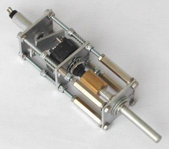
This page describes the construction for the 3-postion rotary switch with "push functionality". The implementation is
very similar to the approach used for the 8-position rotary switch on the KY58 panel.
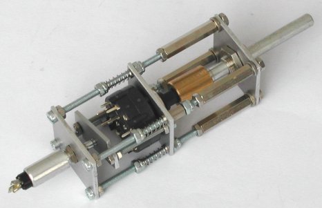
The 3-position rotary switch has a special mechanical functionality (besides 45° steps). You can push the knob. The drawing shows the solution for the rotary switch knobs. The principle is simple. The rotary switch is mounted in such a way that the switch can move. By moving (pushed by the knob), a push-button at the rear side is pressed.
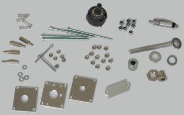
| Parts explanation | |
|---|---|
| A - mounting plate, shaft guide | K - M2.5 x 30 screw |
| B - mounting plate, rotary switch | L - mounting plate, push-button actuator |
| C - mounting plate, push-button | N - M3 nut (red = self-locking) |
| D - knob shaft | R - distance rings |
| E - shaft guide | V - spring |
| F - AUDIO1 panel backplate | S - rotary switch |
| H - push-button switch | X - shaft coupler |
The assembly is mounted on the AUDIO1 panel backplate {F} using a shaft guide {E}. This time I did
not used a "donor potentiometer", but bought a shaft guide for a 6 mm shaft, because it has a quite thin mounting flange. Mounting
the thin flange at the front side leaves more movement space for the push action of the knob and keeps the knob nicely in the
opening of the panel (that is, the knob does not protude much).
The (small) aluminum mounting plates {A}, {B}, and {C} are just 30 x 32 mm. The needed holes are drilled while holding the three
metal plates stacked, to make the alignment of the holes as perfect as possible. The 30 mm width of the metal plates cannot be
larger, because two of these contraptions must be mounted next to each other. The 32 mm height is just 2 mm more (...). This
height keeps the metal plate "within" the dimension of the AUDIO1 backplate at the bottom, and
adds a little space that is needed for the M2.5 screws that mount the mounting plate {L}.
The shaft of the 45° step angle rotary switch {S} is too short, so the 6 mm shaft of a "donor potentiometer" is used together with
a shaft coupler {X}. This adds to the total depth of the construction. More depth is added because of the rotary switch. You need
space between the mounting plate {L} and the connections of the rotary switch. Further, some depth is added by the length of the
push-button {H} at the end of the assembly. The theoretical drawing looks nice, but the maximum length M3 screws that I could get
is 70 mm, and that is some 10 mm too short. So, I used the M3x70 screws plus 15 mm long hexagonal stand-offs with M3 threading.
The complete assembly is not fixed-mounted on the AUDIO1 backplate (as with the
KY58 rotary switch), because the AUDIO1 panel needs two of these.
The complete assembly is mounted on the AUDIO1 backplate with the shaft guide {E}. The rings {R}
create the distance between mounting plate {A} and the AUDIO1 backplate, required for the heads of
the four M3x70 screws.
Mounting plate {A} and {C} are fixed-mounted on the M3x70 screws, but mounting plate {B} slides over the threading. The rotary
switch {S} is mounted on the mounting plate {B}, but right next to the rotary switch are two M2.5 screws {K} mounted. At the
other end of the M2.5 screws is a small rectangular plate {L}. When you push the shaft {D}, mounting plate {B} and {L} move.
The position of mounting plate {B} is such that when the knob is not pushed, the mounting plate {L} is against the top of the
push-button {H}. So, when you push the knob, the push-button is pressed.
The spring-action of the push-button might be enough to push the mechanical construction back to its initial position, but it
might not be enough depending on the type of push-button. Further, as the push-button pushes at a "single point", it may cause
the metal plate {B} to slide back "slanted" (and even worse, get stuck). For these reasons, I added springs on the four M3x70
screws. These springs already put a little "pre-tension" on the metal plate {B}. Using self-locking nuts you can set the position
of the springs. I got four identical springs from four cheap identical ballpoints. Self-locking nuts {N1} define the rest position
and should be set such that the push-button is barely pressed, but pressed! Self-locking nuts {N2} define, together with the
spring in the push-button, the force needed to activate TONE by pushing the knob.
The picture shows the holes for the metal plate {B}. Metal plates {A} and {C} are identical, but only have the 3 mm holes in
the corners and the (correct-sized) hole in the center for the shaft guide / push-button.
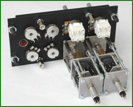
This is the result of two hours of work ... not bad!
|
|
Note. The M2.5 screws {K} are close to the M3 screws, due to very limited space. Make sure that the M2.5 nut can move freely next to the self-locking M3 screw. They may never touch! In the picture you can see that I used small bushings. Those bushings are just a tiny bit thinner than the M2.5 nut, which did touch the M3 self-locking screw ...
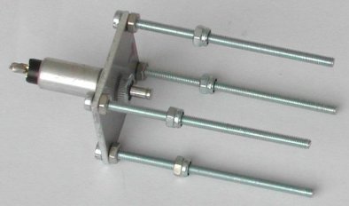
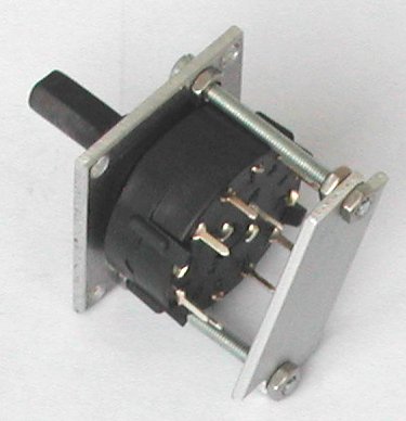
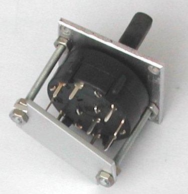
And here are a few more pictures of the assembly steps.
|
|
| components for the assembly | push-button and self-locking nuts N2 |
|---|---|
|
|
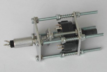
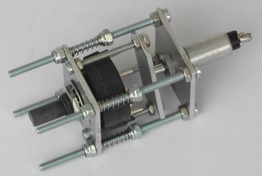
| rotary switch with push-button plate (1) | rotary switch with push-button plate (2) |
|
|
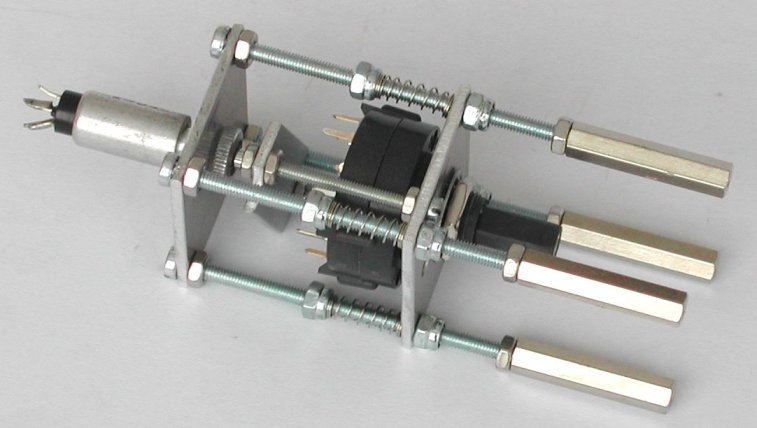
| push-button / rotary switch / N2, N1 and springs (1) | push-button / rotary switch / N1, N2 and springs (2) |
| |
| just mounting plate {A} with shaft and shaft guide to install when the complete assembly is mounted on the AUDIO1 backplate | |
The assembly of the panel is fairly straight-forward. Between the backplate and the panel is the circuit board with the SMD LEDs
for backlighting the panel, as described in the AIR COND panel page. The potmeters and the
AUDIO1 COMM rotary switch assemblies are installed on the backplate. As these assemblies are mounted with just one nut
(the shaft guide), which is rather difficult to tighten, I drilled a small 2 mm hole through the backplate, backlight circuit
board and the first metal plate of each assembly. The hole in the circuit board is a bit larger, so that an M2 screw is "buried".
The M2 screw holds the assembly at its place without the possibility of even the slightest rotation of the entire assembly.
I bought the potmeters with the OFF/ON switch for the COMM1 and COMM2 volume control from RS Online.
The nice thing about these potmeters is that the OFF/ON switch is "double pole", that is, there are
two seperate contacts. As I still cannot run BMS (my PC is too old with an integrated slow not-compatible on-board VGA
port), I do not (yet) know how the ON switch contact on the COMM1 and COMM2 potmeter is used. I do know
that the ON switch is used, and COMM1 switches the power to the UHF panel. But is that switching
ON done directly by switching power, or indicrectly via software? Well, with these potmeters I do
not have to worry about that now! I simply wire one pole with the anti-ghosting diode so that the switch can be connected in
the switch matrix, and the other switch contact is directly available on the sub-D High-Density connector. So, whatever I need,
it is available ...
The schematic shows how I wired the switches of the AUDIO1 panel. As you can see, I used 5 column
wires (D0 ~ D4) and 2 row wires ("common", one for COMM1 and one for COMM2) of the switch matrix. Each switch contact has its
required anti-ghosting diode. As the wires from both rotary switches move a little (when the TONE
knob is pushed), I mounted a small contact strip above the assemblies. These strips were used in the vacuum tube era, but are
still available in the better electronics shops. The strip allows the wiring of the rotary switches without the connector
mounting plate installed, which makes the wiring task easier. One 15-pin High-Density connector (size identical to a standard
9-pin sub-D connector) is needed for all switch contacts.
A standard 8-pin socket (as used on "CB" radios) has just enough pins for the 6 analog signals from the potmeters plus GND and the +5 Volt for their power supply. Thus, the cable for the analog signals can be a separate shielded connection to the PHCC Motherboard's analog inputs. A small capacitor of 10 to 47 nF between the wiper contact of each potmeter and the GND connection reduces noise (thus analog value reading fluctuations), and one 100 nF capacitor between GND and +5 Volt makes the power supply a bit "cleaner".
Finally, one 9-pin sub-D connector connects the backlight LEDs. As space is limited on the connector mounting plate, I had to violate my own rule: the power supply for the LED backlighting is always connected with a dedicated connector, to minimize cross-talk interference from the dimmer PWM signal to any other signal, especially switch inputs and analog (input) signals. At one "edge" are the 2 wires for the backlight power supply, and at the other "edge" are 4 wires to connect the switches of the neighbor panel AUDIO2.
 |
 |