Cool instrument ... a bit more complex to build

| Fuel Quantity Indicator Cool instrument ... a bit more complex to build |
|
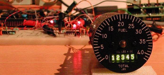
On the Right Aux Panel next to the Compass is the Fuel Quantity Indicator. This indicator is a little more complex, because it has
two needle pointers and a 5-digit numeric drum counter showing the consumed fuel quantity. The needles
are marked "F | R" and "A | L" and show the remaining fuel in the tanks. The drum counter shows the total fuel remaining.
All together, this is a cool looking instrument. You can buy a complete FQI from Vipercore, but I wanted to try building my own FQI.
A tube with the correct diameter is a little difficult to find, the diameter is 2.25 inch. Jan ("cavalier6X")
had a 2.25 inch tube with the glass and dial installed, made by "Nigel". Unfortunately, it was a mock-up, with the
needle pointers glued on the dial. Even worse, the glass with the closing ring was glued on the tube with SuperGlue, so there is no
chance of opening the front side without serious damage to the nearly irreplacable front. Jan had a spare dial, no longer needed,
so this build will describe the construction of the FQI completely done from the rear side. No messing around with the closing
ring and glass, just leaving it as it is. It does imply that I will have to remove the installed dial from the rear side, because
I need to get the needle pointer at the front side of the dial! I hate to say it, but it could only be removed by destroying that
dial. After removing the dial, I could slide in an almost fitting tube and press on the glass. There was some play, and that gave
me hope ... with a pointy surgeon knife I was able to carefully cut the SuperGlue. The closing ring became loose without damage.
Only the dial did not survive, but Jan also had a "Vipercore" dial that he did not need anymore, because he had bought the
complete Fuel Quantity Indicator from "Vipercore". Now I can place the dial into the tube from the front side and let it rest on
the ring inside the tube.
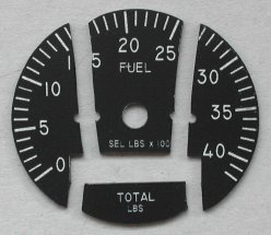
The spare dial came with the post in an envelop glued with adhesive tape to a sheet of paper.
Unfortunately the mail man does not always care much about his deliveries, so by the time that envelop was on my doormat the dial
was broken in four parts ... bummer! The picture shows the 4 parts, already filed to fit the 2.25 inch tube.
When I put the parts together and hold a bright light source behind the dial some light shines through the "break-lines". I solved
this problem by coloring the "break-edges" black with a waterproof feltpen. Then I glued the 4 parts together. The result was quite
nice, and I am happy with it as it is now. Just for strength I glued a thin piece of plastic onto the rear side of the dial. That
piece of plastic was cut with a Dremel out of the cover of a CD-ROM jewel case.
The tricky steps are the mechanical construction for the two indicator needle pointers and the display. I did an inventory of
available dot-matrix displays which also comes in handy when I start the construction of the CMDS panel. The needle pointers will
be controlled using aircores.
Needle pointers
The needle pointers can be controlled each by an aircore. You can read more about aircores in the "Aircore indicators" page,
describing the "steam engines" of the pit (OIL, NOZ POS,
RPM, and FTIT). The difficulty here is of course the fact that there
are two needle pointers, thus two shafts.
One solution for the required mechanism is the following. The needle pointer on the top (closest to the glass) is directly
driven by the first aircore. The needle pointer closest to the dial is mounted on a thin wire. This wire rotates around the shaft
of the first aircore. Behind the dial this wire has a larger "U" shape around the first aircore and is attached to the shaft of
the second aircore.
Another approach to realize the two shafts is by using the mechanism of a battery operated clock. A battery operated clock can be
bought for just a few Euros; check that the model only has the minute and hour hand. No seconds hand is needed. Maybe the toothed
gears of the clock can be used to make the installation of the aircores easier.
I have not yet decided which method I will use. First, I will make a few sketch drawings to see what is easiest to implement.
Total fuel quantity display
The total fuel quantity remaining mechanical 5-digit drum counter is build using a 5-digit dot-matrix display. This display is not
available in your local electronic parts shop, so the solution is either to use a readily available 4-digit dot-matrix display, or
do the construction like the FQI from Vipercore: use 8-digits and have 3 digits hidden behind the dial! I did some searching
on the internet to find out which dot-matrix displays are available. Limiting the search parameters to the color green and the
height of the digits smaller than 6 mm, I came to the following lists. Maybe they are useful for making your choice ...
| source | type code | number of characters | character height | supply voltage |
light intensity | interface |
|---|---|---|---|---|---|---|
| OSRAM | DLG2416 | 4 x 1 | 5.08 mm | 5 V | 120 �cd | data/address |
| OSRAM | SLG2016 | 4 x 1 | 4.72 mm | 5 V | 75 �cd | data/address |
| AVAGO | HDSP-2113 | 8 x 1 | 4.81 mm | 5 V | 210 �cd | data/address |
These 3 displays each have a height that is unique. Two or four displays (8 or 4 characters) can be combined to 16 characters (4 x 4) for the CMDS display group. The height of the characters is close to the maximum for the Fuel Quantity Indicator. The DLG2416 is physically too high to make it fit behind the FQI bezel. It height will block the axes of the needle pointers!
| source | type code | number of characters | character height | supply voltage |
light intensity | interface |
|---|---|---|---|---|---|---|
| OSRAM | SCDQ5543R | 4 x 1 | 3.2 mm | 5 V | 5.4 mcd | serial |
| OSRAM | SCDQ5543Q | 4 x 1 | 3.2 mm | 5 V | 5.4 mcd | serial |
These 2 displays have a small character height, but are only available as a 4-character device. Similar 8-character devices (though the character height is a little higher) are cheaper than two 4-character devices. For the CMDS panel you would need 4 of these devices, which gets all together a little expensive.
| source | type code | number of characters | character height | supply voltage |
light intensity | interface |
|---|---|---|---|---|---|---|
| AVAGO | HCMS-3917 | 8 x 1 | 3.71 mm | 3.3 V | 100 �cd | serial |
| AVAGO | HCMS-3907 | 4 x 1 | 3.71 mm | 3.3 V | 100 �cd | serial |
| AVAGO | HCMS-2913 | 8 x 1 | 3.71 mm | 5 V | 114 �cd | serial |
The 8-character 5 Volt device HCMS-2913 is a good option for the FQI indicator. The character height of 3.71 mm is used in the Fuel Quantity Indicator version with small displays (of Vipercore). This device could also be used for the display group of the CMDS panel, but the character height is actually a bit too small for the CMDS display.
| source | type code | number of characters | character height | supply voltage |
light intensity | interface |
|---|---|---|---|---|---|---|
| AVAGO | HCMS-3977 | 8 x 1 | 4.57 mm | 3.3 V | 100 �cd | serial |
| AVAGO | HCMS-3967 | 4 x 1 | 4.57 mm | 3.3 V | 100 �cd | serial |
| OSRAM | SCE5783 | 8 x 1 | 4.57 mm | 5 V | 150 �cd | serial |
| AVAGO | HCMS-2963 | 4 x 1 | 4.57 mm | 5 V | 114 �cd | serial |
| AVAGO | HCMS-2973 | 8 x 1 | 4.57 mm | 5 V | 114 �cd | serial |
| AVAGO | HDSP-2533 | 8 x 1 | 4.57 mm | 5 V | 210 �cd | data/address |
The 4.57 mm character height seems to be the most common. A 16-character group can be created by 4-character and 8-character
devices in either 5 Volt and 3.3 Volt technology.
The AVAGO HDSP-2533 is the only device with a character ROM, thus the dot-matrix character presentation is coded in the device (it
has 16 user-programmable characters). Due to the character ROM the interfacing is very simple, and can be realised with standard
(non-multiplexed!) digital outputs. The HDSP-2533 also has the highest brightness, making it a good choice for the CMDS panel.
All displays except the HDSP-2533 are interfaced using a serial communication protocol. Hardware-wise this is nice, because the device has just a few pins, so the hardware I/O is simple. However, nothing comes free; the software to control serial displays is more complex, and it will require a dedicated PIC (and software) to control this type of display.
Another aspect is the physical length of the display. For the Fuel Quantity Indicator 5 digits are needed, thus it makes sense to
use one 8-character device for the FQI. However, the available space for the length is limited. The SLG2016 is 4-characters and its
length is 19.91 mm, so two SLG2016 will need a space of approx 40 mm (char height is 4.57 mm). A single HDSP-2113 is also 8
characters (height is 4.81 mm) but the required space is approximately 43 mm. Note that the SLG2016 and the HDSP-2113 have on-board
character ROM and need a simple interface.
The CMDS panel has four positions and each position has four characters. The width of the opening is approx 8 mm high and 82 mm
wide. Note that the left 2 positions are just 20 mm each, so in total 40 mm, whereas the right 2 positions are each approx 21 mm,
so in total 42 mm.
Dial illumination
The numbers on the dial and the indicator division lines are illuminated to enable read-out in the dark. Just as the "steam
engine" indicators (OIL,
Conclusions
The mechanism for the two needle pointers is ripped from an obscure 3 inch indicator that had two needles. The needle on the
center axis was driven by a servo (via several gears) and the needle on the outer axis was driven by a large gear driven by a
knob at the lower left side of the instrument. Most parts of the instrument are discarded. How to drive the two shafts will
yet have to be figured out ...!
To keep the hardware simple, the displays chosen for the Fuel Quantity Indicator are not of the serial communication type, but use data and address lines to display data. This type of display requires more connection wires, but the big advantage is that it does not need local intelligence (PIC) to load the character presentation data at power-up (these devices do not have a ROM that stores the dot-matrix codes for each character) and no serial communication protocol needs to be written to interface the displays. Further, to simplify the hardware interface, it is a requirement that the displays operate at 5 Volt power supply. This implies that the choice for the displays is narrowed down to one HDSP-2533 device or two SLG2016 devices. The physical length of the HDSP-2533 is 43 mm which will be difficult to fit inside the tube! So, the choice is limited to just one type: the SLG2016 display is almost 20 mm, so two next to each other is 40 mm, which will fit inside the tube.
In a local RC hobby shop I bought two sets of small plastic gears, hoping that they would be useful ... it turned out that they
are just great for the job! Keep in mind that whatever you plan using gears, it must all fit inside the approximately 50 mm
diameter tube! The gears are needed for two reasons. First, given the gears, I think that small aircore motors are not
powerfull enough to drive the needle pointers. Using cheap small RC servos (with a rotation of at max 180 degrees) I would also
need gear anyway, but I could also implement a gear ratio. The servos I use are 9 grams and can be bought on eBay for just $5
(or even less!). I already had built a PHCC Servo Daughterboard, and the Stepper/Aircore board was already in use for the "steam
engines" indicators. Because of the gear ratio, the larger gear on the servo has a diameter just a little larger than half the
diameter of the tube. That means that the two driving shafts must go past the inner shaft length of the butchered original
instrument.
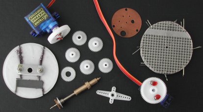
The picture shows the repaired dial with the CD-ROM jewel case piece glued on the rear side and the aluminum bracket (remainder)
of the original instrument to guide the outer shaft, a 9 gram servo with the larger gear already mounted on the servo shaft, the
small gears with the two axis hole enlarged gears top and bottom and the original inner and outer shaft. Next to the shafts is
a piece used to mount the large gear on the servo axis using two M2 screws, fixed with a drop of my wife's nail varnish! The
copper disk comes out of the original instrument to hold the other end of the inner indicator needle shaft centered. At the right
side you see a stack of circular filed pieces of circuit board, kept centered at 8 corners with a piece of wire through the holes.
That makes it easy to drill holes through all circuit boards while keeping the holes aligned.
I did not yet have the two SLG2016 displays, but their placement on the board is critical. They need to be installed right behind
the opening in the dial of course, but also fitting in the tube horizontally, while having exactly 5 digits visible in the opening.
First, I drilled a 2 mm center hole through the entire pack of circuit boards (the construction "disks"). Then I put an M2 screw
throught the center hole and placed a small gear on it. Now, using two other gears against the center gear I was able to drill the
two holes required for these two shafts. These two shafts will drive the two indicator needles by the servos mounted at the rear
side. Finally, I drilled one M2 hole "below the display" and two 2.5 mm holes at the upper side of all disks. These holes are used
to mount the disks at the needed distance from each other. After all these holes the wires at the corner are no longer needed and
can be removed. Time to build everything together.
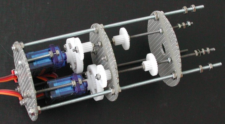
The small gears slide over the M2 threaded rod, so to lock those gears on the threaded rod I use a droplet of washing up liquid from the kitchen! The washing up liquid is slippery, but when it has dried it holds almost as good as superglue. The nice part about this is that you can "dissolve" this glue with just a drop of water! To make sure that the gears stay locked to the M2 threaded rod the small gears are clamped with two M2 screws (locking each other) at each side. I know, the picture only shows one screw, but this picture was taken while it was all still in the constructional phase. Likewise, two M2 screws are used at opposite sides of each disk. The threaded M2 rod must be able to rotate freely in the hole in the disk, but may not move laterally.
Missing from the picture is the inner and outer shaft. The distance between the middle disk and the disk at the right side is correct, and the two small gears are at the correct position. The space between these two disks is that much, because that is the lenght of the inner and outer shaft. They rotate so smoothly, I don't dare to shorten those axes without getting into trouble.
Displays arrived, but ...!
The display board mounts with the 3 threaded rods to the mechanical assembly at the rear side, and with the two M2 screws the
front dial is mounted to this circuit board. The center hole in the circuit board is large enough to move the thickest part of the
outer shaft through the hole to enable construction and disassembly at a later time (you never know what may happen in the future).
The SLG2016 displays from Digi-Key (USA) arrived. Time to make the most important disk; the disk with the electronic stuff: two
displays and some SMT LEDs (and series resistors) for dial illumination. After placing the two displays on the circuit board and
aligning the displays for the opening in the dial, the circuit board is cut to its 50 mm diameter circular shape. Note that you
first determine the position of the displays and then cut the circular shape of the circuit board to fit inside
the tube!
 I assume that the Fuel Quantity Indicator from Vipercore uses the SLG2016 displays, and that works great (as you can see on the
Vipercore website). But that Fuel Quantity Indicator construction does not use a tube ... I was optimistic that
the displays would fit inside the tube, but because of the 5x7 dot-matrix display alignment behind the opening in the dial, one
side will protrude for a few millimeters from the dial. "That is OK" I thought, "I will cut a slit in
the tube to give the protruding edge of the display some space" ... bummer, that will not suffice for yet an other
millimeter. And there it ends, because when I install the Fuel Quantity Indicator tube in the Right AUX Console, the tube
will be held by the clamp. And when tightening the clamp it is very likely that the protruding display will be damaged. So, back
to the list of available displays. The SLG2016's are not wasted money, because they will be great in the CMDS panel.
I assume that the Fuel Quantity Indicator from Vipercore uses the SLG2016 displays, and that works great (as you can see on the
Vipercore website). But that Fuel Quantity Indicator construction does not use a tube ... I was optimistic that
the displays would fit inside the tube, but because of the 5x7 dot-matrix display alignment behind the opening in the dial, one
side will protrude for a few millimeters from the dial. "That is OK" I thought, "I will cut a slit in
the tube to give the protruding edge of the display some space" ... bummer, that will not suffice for yet an other
millimeter. And there it ends, because when I install the Fuel Quantity Indicator tube in the Right AUX Console, the tube
will be held by the clamp. And when tightening the clamp it is very likely that the protruding display will be damaged. So, back
to the list of available displays. The SLG2016's are not wasted money, because they will be great in the CMDS panel.
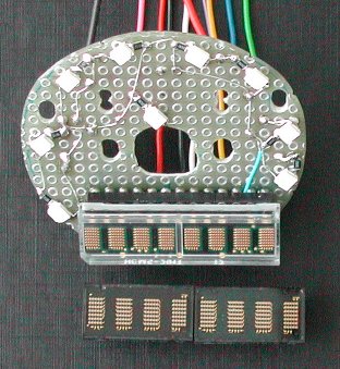
The new display that I selected is the HCMS-2913. On the picture you can see the HCMS-2913 installed in the socket on the circuit
board. The SMT LEDs are also soldered, and the tiny black "things" next to the LEDs are the resistors. The SLG2016's are below the
HCMS-2913 for comparison. Together, they are almost a complete digit larger! The character height of the HCMS-2913 is slightly
smaller than the SLG2016. The height is 3,71 mm, and that is identical to the height of the smaller display version of the Fuel
Quantity Indicator on Vipercore. The physical length of the HCMS-2913 is just some 35,6 mm, so that would give me the few
millimeters that I need at one side inside the tube ... The major drawback of this display is the method to control it. It uses a
serial data protocol to send the dot presentation on the display. The display does not contain a ROM (Read-Only Memory) that holds
the dot-matrix character presentation patterns. The data patterns must be created and sent by external logic, so a PIC is needed
to control the display. But let's look at the sunny side of this display: it uses less wires to connect.
After placing the display on the board and making the board fit inside the tube, you can solder the backlight SMT LEDs with their
series-resistor. By moving the first mounting disk a bit to the rear side it is even possible to create space to mount the
expensive display on machined pin IC sockets (
The distance of the display board with the front dial to the first mechanical construction disk is such that the outer shaft can rotate freely in the small flat aluminum strip, but does not have too much play in lateral direction. The small flat aluminum strip guides the outer shaft and is mounted onto the rear side of the dial. The aluminum strip was cut out of the plate that was in the original instrument behind the face plate, because it also guided the shaft in the instrument, thus a perfect fit. The length of the strip is cut small to prevent blocking the illumination of the dial, and the width is also small to have room for the display. Two 2 mm holes were drilled in the aluminum strip to mount the strip behind the FQI dial with M2 screws of which the screw head is painted black. These two screws also mount the circuit board with the display and backlight SMT LEDs. A 1 mm thin small piece of green plexiglass just a little larger than the opening in the dial is glued on the transparent plexiglass. Without the green plexiglass the display (and its dot-matrix LED groupings) is very clearly visible. The green plexiglass nicely "hides" the display physical appearance thrugh the opening in the dial.
As the two servos are mounted on the last mounting disk, I simply filed two small rectanglar openings at the rim of the disk to guide the 3-wire cable for each servo through. The wiring to the display is done with thin wires from a 25-conductor cable. In total, 8 wires are needed to connect the display. Five wires run at one side of the M2.5 threaded rod to the rear side, and the other five wires (backlighting!) run at the other side. At the rim of each mounting disk a rectangular piece is filed away to let the wires pass through when everything is mounted in the tube. The two wires for the dial backlighting are also routed to the rear side through these openings. The thin wires are kept in the opening with a thicker solid wire. The solid wire is simply held by holes in the circuit boards.
On the rear closing plate of the tube I mounted two 9-pin D-SUB connectors, one female D-SUB and one male D-SUB to avoid wrong connection errors! One 9-pin D-SUB connects the display and the other 9-pin D-SUB connects the backlighting LEDs and servos.
After wiring a bread-board for a PIC 18F252, and connecting the few wires needed to operate the HCMS-2913 display, it was time to write some software. These are the pins of the display that you need to make the display come alive.
| sub-address | function |
|---|---|
| 0 ... 4 | The five character positions for the Fuel Quantity Indicator. sub-address 0 represents the left-most (visible) digit of the 5-digit value, sub-address 4 represents the right-most (visible) digit. The data byte must be either a "SPACE" or one of the (ASCII) numerals 0 .. 9. Note that the first two and last physically digit are hidden behind the Fuel Quantity Indicator dial. |
| 5 | Set display intensity, data byte range 0 ... 63. If the data byte value is > 63 (0x3F), the command is ignored. |
| 6 | Reset HCMS-2913 display (pulse on RST* input), data byte value irrelevant. |
| 7 | Set diagnostic LED usage mode. The data byte value defines the LED usage mode. "0" :: DIAG LED always OFF. "1" :: DIAG LED changes state every received (valid) PHCC command "ACK". "2" :: "Heart-beat" mode. As long as the software runs OK, the LED flashes at a rate of 1 Hz. |
| 8 | Set 8 user-definable outputs "D0 - D7". D0 :: data bit #0 ... D7 :: data bit #7. |
| 9 | Set 6 user-definable outputs "D8 - D13". D8 :: data bit #0 ... D13 :: data bit #5. Data bit #6 and data bit #7 are not used. |
As you can see, the sub-addresses 8 and 9 control 14 digital outputs. The HMCS-2913 display only needs 5 output pins, so there
were a few I/O pins of the PIC not used. I used one I/O pin to connect a "diagnostic indcator" LED. That pin (RA4) is the only
open-collector output, thus always needs a pull-up resistor. The LED with series-resistor is a nice option.
The remaining I/O pins are all programmed to operate as an output. You can connect driver ICs to these pins (just like the PHCC
40 Digital Output daughterboard), and control lamps, coils, or whatever.
to be continued ...