115 Volts AC at 400 Hz put to use ...

| LIQUID OXYGEN indicator 115 Volts AC at 400 Hz put to use ... |
|
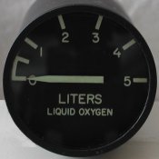
The Liquid Oxygen Indicator is another instrument on the AUX panel at the right side. The indicator has a diameter of 2 inches. The Liquid Oxygen Indicator (LOX) in the F-16 uses a capacitive sensor (as far as I know) to measure the quantity of liquid oxygen in the tank. The designation for the F-16 indicator is GMU-37/A. However, this page describes the LOX of the Starfighter (F-104). The difference between the F-16 and F-104 version is immediately seen when you look at the connector at the rear side. The F-16 LOX indicator has 6 pins surrounding the coaxial connection in the center, whereas the F-104 LOX has 8 pins surrounding the coaxial connection. Strange that the F-16 has internal instrument lighting and the F-104 does not have lamps inside, but has more connection pins!
|
The picture shows a view at the rear side on to the connector. I have this connection information from "Auke104" on Viperpits.
|
Note that the coaxial connection and shield has no designated letter. The letters "G" and "I" are not used. |
The LOX indicator can not be opened, it is sealed air-tight. Inside the indicator are quite some electronic parts.
In the liquid oxygen tank is a capacitor installed. This capacitor consists of concentric shaped tubes, and the capacitance is
an exact representation for the amount of liquid oxygen in the tank. In the LOX indicator is a bridge circuit and the capacitor
in the liquid oxygen tank is part of that bridge. If the amount of liquid oxygen changes, the capacitance changes and as a
consequence, the bridge is no longer in balance. The error signal is amplified by a 3-stage amplifier and drives the coil of
a motor. On the shaft of the motor is the needle pointer mounted. The shaft also drives a potentiometer via gears. The
resistance of the potentiometer is also part of the bridge. The motor shaft rotates until the bridge is in balance again.
The power supply for the bridge and the internal electronics is derived from the external power supply which is 115 Volt AC at
400 Hz.
The little documentation available of the GMU-37/A (the LOX indicator used in the F-16) specifies that the capacitance of the
sensor is between 60 and 67 pF for the "zero" reading, and approximately 96 pF for "5" reading (full scale).
Of course, we want the LOX indicator functional in the pit without modifications to the instrument.
The 115 Volt AC 400 Hz power supply is already described on another page (see "Altimeter"). So, how to fake the capacitive sensor?
We can use a varicap diode for this purpose. A varicap diode is basically a diode of which the capacitance is controlled by the
voltage across the diode. The voltage level for the varicap is controlled by an analog output from the interface hardware.
So far for the theory
I connected the 115 Volt 400 Hz power supply to pins B and J. The motor starts to rotate counter-clockwise, and never stops.
That seems logical as there is no sensor connected. However, when I simply connect a capacitor of 68 pF to the coaxial input
(between center pin and shield) the motor continues to rotate ... "Ripley" suggested that the capacitor might have to be connected
between the shielded lead (coaxial center pin) and the unshielded lead (pin "H"). That's the solution!
|
I used a few ceramic small capacitors which I had on my desk. As you can see the indicator is "0" when the capacitance is 78 pF,
and the indication is "5" with a capacitance of 115 pF. The shielding for the coaxial center pin wire is a must. If I put my
finger at 5 cm from the coaxial center pin wire, the meter moves. If I touch that wire, the meter rotates almost 70 degrees
counter-clockwise! If I put my finger near the "H" wire or even touch it, it has no effect on the indication. Conclusion: shielding is necessary, hence the control circuit to mimic the capacitance of the sensor must be quite stable. |
|
|
First I had so find a suitable varactor diode. The needed capacitance is in the range of 70 pF to 120 pF, that is a range of some 50 pF. Common UHF varactors do not have such a large range, so I started looking for (older) type VHF varactors. Another requirement is of course that my local supply shop has them. Ordering just a few components is too expensive, because of the shipping cost. I found the varactor BB909B which has a minimum capacitance of approximately 40 pF at 1 Volt and a capacitance of 10 pF at 10 Volts. In this range of some 30 pF the capacitance changes almost linearly with the voltage, and I have the impression that the LOX indicator changes linarly with the capacitance at its input. If that linearity holds true, the software will be easy.
I bought two BB909B varactors to connect them in parallel to obtain the required range. That will set the minimum capacitance to 20 pF and the maximum capacitance to 80 pF. A small trimmer is connected in parallel to set the zero position on the LOX indicator. Such a trimmer always has a certain minimum capacitance, but a small additional capacitor is needed to actually trim the reading to zero with the trimmer.
Note that I mount the "capacitor stuff" as near as possible to the LOX indicator. During experiments, initially I used just 20 cm of normal wire to connect a capacitor to find out the working range as written above. Then I made a proper cable ... as I learned that the "hot" wire from the capacitor (to the center pin of the LOX) is very sensitive to anything happening in its neighborhood, I used 1 meter of RG-174. That is 50 Ohm shielded coaxial cable, used in instrumentation for its flexibility. I made it 1 meter, because I figured that would be the length I would need in the pit. Alas, the capacitance added because of the coaxial cable is so significant, that it was difficult to get the indication down to zero! Another good reason to build the "capacitor stuff" as near as possible to the LOX indicator is just to minimize sensitivity to "external" signals. Still, it is wise to used a shielded cable even if it is just for 10 cm.
I started with the shaded area in the drawing (the components that must be close to the LOX indicator). The 220 pF capacitor is needed to keep the DC adjustment voltage for the varactor away from the LOX indicator input circuit. The two varactors will give the required capacitance range, and the 15 pF capacitor together with the trimmer will adjust the meter indication to zero. However, when I add the 100k resistor with the 100 nF capacitor, the meter starts moving and never stops! Keeping the resistor and removing the capacitor makes the indicator stop at the correct position. No matter what I do, whenever I connect anything to the 100k resistor the meter moves and never stops. The input side of the measuring section of the LOX is a bridge circuit (as far as I know). Back to some theory ...
| The picture shows the principle of the so-called bridge of Wheatstone. It has 4 resistors, a null-detector meter (needle centered and can move to left and right) and is connected to a DC voltage. The voltage level does not matter for the measurement. The null-detector meter indicates a condition of "balance". If the bridge is balanced, the equation holds and the null-detector meter has no deflection, thus is centered. If Rx is higher the meter shows a positive deflection, if Rx is lower the meter shows a deflection in the opposite side. If Rx changes, the bridge can be balanced again by changing R1 or R2. If R1 (or R2) is known, then Rx is also known by working out the ratio. Note that the ratio (equation) is only true when the null-detector meter has no deflection. |
|
If you use an AC voltage, you can substitute the resistors with impedances, for example capacitors. Now, the bridge is balanced
when the impedances match, that is when phase and magnitude of the voltage are equal across the two divider circuits. Such a bridge is also in the LOX indicator. Capacitance Cx is the sensor that has a certain value depending on the amount of liquid oxygen in the tank. Z2 and Z3 may be simple capacitors, but more likely will be resistors in the LOX indicator. In that case, Z1 is a variable capacitor which is mechanically connected to the shaft of the motor (possibly with some gears). The motor also drives the needle of the LOX indicator. With these assumptions, I can explain the operation of the LOX indicator. |
If the amount of liquid oxygen in the tank changes, so does the capacitance of the sensor change. This change creates an unbalance of the bridge. The null-detector meter would show some deflection. However, there is no null-detector meter in the LOX, but this voltage is fed to an amplifier to boost the small voltage to a level to drive the motor. As the motor shaft rotates, so does the needle of the LOX indicator and the capacitance of Z1 changes. When the bridge is in balance again, the voltage to the amplifier is zero, and the motor stops. The needle accurately indicates the amount of liquid oxygen in the tank.
As described in the explanation of the bridge, the components must create a balance. I can set the needle of the LOX indicator to any position by changing the capacitor value on the input terminals of the indicator. As I prefer an electronic solution (no moving mechanical parts), I started an experiment using the varactor diode. The parts drawn in the shaded box (components that must be installed close to the indicator) works ... almost ... The small capacitor, trimmer, varactor, and coupling capacitor of 220 pF are all fine. I can also connect the 100k resistor at the side of the varactor, but as soon as I connect anything to the other side of the 100k resistor, the LOX indicator needle starts to move and never stops. It seems that the added impedance unbalances the bridge. That means I can never control the capacitance of the varactor as that control circuit will always add some impedance that can not be matched by the brdige in the LOX indicator. So, in the end I am afraid that the proposed circuit will not do the trick. Bummer.
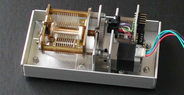
I have to assume that the liquid oxygen sensor represents a "clean" capacitive value, so it can only be mimiced by something that has a "clean" capacitance: a variable capacitor as found in radio equipment (if not replaced by varactors...), or simply fixed capacitors.
 The variable capacitor is a fairly simple mechanical solution: attach a hobby servo to the shaft of the variable capacitor, and
drive the servo under software control: voil�, we have a working LOX indicator. This is a good solution (I think), but you
have to make a mechanical construction. The axis of the servo must be aligned with the shaft of the variable capacitor, best you
use something of a flexible coupling. The variable capacitor must not have some gearing on the shaft and the shaft must rotate as
smooth and light as possible, else you will need a bigger servo.
The variable capacitor is a fairly simple mechanical solution: attach a hobby servo to the shaft of the variable capacitor, and
drive the servo under software control: voil�, we have a working LOX indicator. This is a good solution (I think), but you
have to make a mechanical construction. The axis of the servo must be aligned with the shaft of the variable capacitor, best you
use something of a flexible coupling. The variable capacitor must not have some gearing on the shaft and the shaft must rotate as
smooth and light as possible, else you will need a bigger servo.
Adjustment is as follows, but it depends a little on the variable capacitor that you use. Of course, you want the best result,
so you want the entire range from 0 to 5 realized with the variable capacitor (CV). May be you need a fixed
capacitor and small timmer to set the 0 position (C0 and CT), but it is also possible
that you can get this position with the variable capacitor (almost) in its outer position (when the rotor plates are almost
completely rotated out of the stator plates). If just a small portion of the movement range of the servo will produce the 5
reading, you can experiment with a capacitor in series (Cs) with the variable capacitor, but this is
not easy. As you know, with resistors in series you simply add the values to get the total value and the total value is thus
always larger than the largest individual resistor. But with capacitors in series the resulting capacitance is always lower
than the smallest individual capacitor and the calculation is the reciproke sum of the separate values.
Another solution is electro-mechanical, I think it may be a good solution: a few relays. The coil of each relay is controlled
by a digital output. The relay creates the desired galvanic insulation between the control hardware and the LOX indicator. Each
relay adds a capacitance when the contacts of the relay are closed. If the capacitance is selected with care, you can create 16
discrete positions for the needle of the LOX indicator by using four relays. Three relays would give 8 discrete positions. As the
movement angle of the needle spans 180 degrees, four relays will give a "step size" which is a little more than 11 degrees. If
you want a finer granularity you can add one relay, but stray capacitance will make this difficult to realize.
 As the stray capacitances will vary per soldered board it is best to use a trimmer with each relay. One fixed capacitor plus a
parallel connected trimmer (C0 and CT) is used to set a zero indication when all
relays are in their off position. Keep the wiring as short as possible, because every pF (!) counts.
As the stray capacitances will vary per soldered board it is best to use a trimmer with each relay. One fixed capacitor plus a
parallel connected trimmer (C0 and CT) is used to set a zero indication when all
relays are in their off position. Keep the wiring as short as possible, because every pF (!) counts.
Adjustment is simple. First use the trimmer to set the needle to the zero position when all relays are not energized. Then
energize the relay connected to the "most significant bit". Adjust the trimmer (C4) connected to this relay
until the needle points at a read-out of 2,5. If you can not reach the 2,5 indication you must add a small fixed capacitor across
the trimmer. I can not give specific values as it depends on the wiring and the trimmer you use. Nice would be a trimmer adjustment
somewhere "mid-range". If you have to add a fixed capacitor, my guess it will be in the range of 10 pF.
Now de-energize the "msb" relay and check that the needle returns to zero. Activate the "msb - 1" relay. With its trimmer
(C2) set the needle to 1,25. Check that when you activate the "msb" relay, the needle moves to "3,75".
Repeat this procedure for the next relay to the smallest "step size". It is now clear that for the smaller "step size" increment
the required additional capacitance is so little that perhaps the closing contact of a relay is already too much!
After building a 115 Volt 400 Hz power supply, two possible solutions are available to control the needle of the LOX indicator.
The electro-mechanical solution uses a few relays. Each relay adds a fixed (trimmed) capacitance.