Buy or DIY ?

| 400 Hz POWER SUPPLIES Buy or DIY ? |
|
Over time I have been busy finding a good solution for the 400 Hz power supplies. You need 400 Hz power supplies in your pit only if you are using original instruments such as the altimeter, ADI and HSI. The altimeter and ADI need 115V AC 400 Hz, the HSI needs this voltage also, and 26V AC 400 Hz.
Technical available solutions
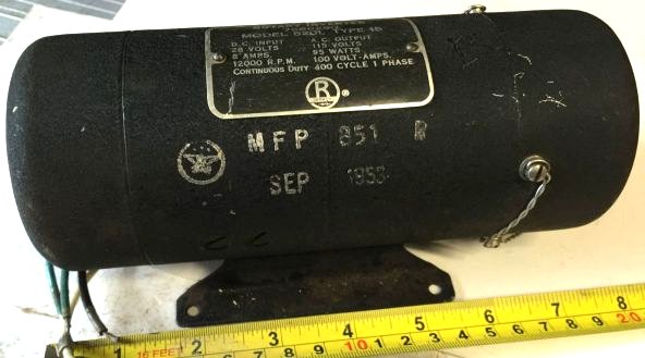
The oldest method to generate an AC 400 Hz voltage (for our purpose) is using a rotary inverter. This is in principle a motor,
driven by a DC voltage, mechanically linked to a generator. The output of the generator is the needed AC 400 Hz voltage and can
be single phase or three phase.
This solution is straight-forward, but has a few drawbacks.
The more modern solution to generate an AC 400 Hz voltage is using a static inverter. This type of inverter uses electronics and one or more transformers to generate the AC 400 Hz output from a DC power input. Although there are no moving parts, just electronics, does not mean they are "silent". The static inverters that I have seen all make noise - typical the 400 Hz tone is audible. But if the static inverter is built inside a box (note that there must be some ventilation as all electronic hardware generates heat!), that noise can be acceptable.
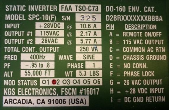
If you plan to buy a static inverter of eBay, check very carefully whether the output is 400 Hz!
Static inverters may also have AC output at some other frequency, for example 50 Hz or 60 Hz,
which for our purpose,
are no good!
Do It Yourself possibilities ?
As rotary inverters are not a good solution, and static inverters (mostly via eBay) are not cheap and difficult to repair,
the question is whether it can be possible to come up with a simple "DIY" 115V AC 400 Hz power supply. The inevitable transformer
is the most difficult part, but I found that transformers designed for 50/60 Hz operation seem to work "OK" at 400 Hz. This may
not be true for all 50/60 Hz transformers, but the model I used worked fine. By the way, if you have a suitable 400 Hz transformer,
use it. It has a much better efficiency and weighs less (less iron needed, due to the higher frequency).
I have two solutions for the 115V AC 400 Hz power supply voltage. Both solutions use an "of-the-shelf" 30W transformer which has
two 115V primary coils and two 18V secondary coils. In normal use, this transformer can be used for 115V and 230V mains (primary
coils parallel or in series, respectively) and the output voltage can be 18V or 36V (secondary coils parallel or in series,
respectively).
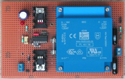
Option #1 - MOSFETs (square wave drive)
My first solution uses two MOSFETs that each drive a part of the secondary coil of the transformer. These MOSFETs are
switched on and off one at a time, thus building up an ever-changing magnetic field.
As MOSFETs are either in a conducting state or not, the oscillator that drives the gates of the MOSFETs is a block wave. The
coils of the transformer cannot follow the block wave, thus the output voltage at the primary coil will not be a block
wave, but it certainly is not a clean sine wave either. The shape of the output voltage can be improved by adding one or two
capacitors of 0.47 microFarads in parallel across the coil. Note that the operating voltage of these capacitor must be at
minimum 250V (400V is better).
The block wave oscillator can be built using standard CMOS ICs, such as the CD4047 to generate the two complementary signals.
A more detailed description of this design is in the "Center Console -> Altimeter" page.
Although this design works fine, it has a significant drawback.
The DC power supply voltage defines the output AC 400 Hz output voltage. Depending on the design of the block wave oscillator
there might be an issue with a changing DC power supply voltage. Perhaps the frequency shifts when you adjust the DC input
voltage or maybe the DC input voltage needs to be so high (to obtain 115V at the output) that the chosen oscillator components
cannot handle that. So, this design is not so easy, also because it requires its own DC power supply (to set the 115V output
amplitude).
Another drawback is that transformers, in general, are designed for sine wave voltages. A block wave sure is not a sine wave,
but I do not know what the effect is using block wave voltages.
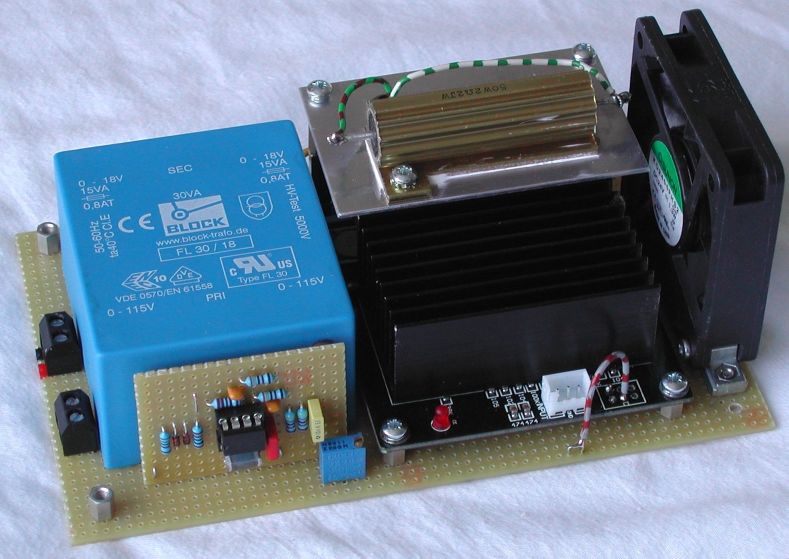
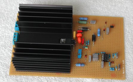
Option #2 - Audio class-D amplifier (sine wave drive)
The main component of the second solution is a cheap class-D amplifier which you can buy on eBay. From a local seller you pay some $20 to $25 and have the amplifier within a week. However, if you buy the same amplifier from China or Hong Kong, it will cost less than $10, but you have to wait up to 3 weeks for it to be delivered by the postman. This design is simple and works on a standard 24V DC power supply. The principle is a standard audio amplifier, but instead of driving a loudspeaker (which is a coil), the amplifier drives the secondary coil of the transformer. The signal input of the amplifier is connected to a sine wave generator (at 400 Hz of course). The volume control of the amplifier sets the 115V output amplitude of the primary coil of the transformer. A more detailed description of this design is in the "Center Console -> ADI" page.
What about 3-phase 115V AC 400 Hz ?
Maybe you need a 3-phase 115V AC 400 Hz power source in the simulator. The Standby ADI in the F-16 is an example of this. The
gyro inside the SADI runs on 3-phase power. It is cool to hear the gyro spin up after power is applied, but for the rest it
does not have much use, unless your sim is built on a moving platform ...
You can build a 3-phase 115V AC 400 Hz power supply yourself, based on the above mentioned option #1 and option #2.
Option #1 - MOSFETs
To create 3 pairs of complementary signals at 120 degrees phase shift from each other, the design with the CD4047 is slightly
changed. The oscillator runs at a higher frequency and the output clocks a 4017 counter. The 120 degrees phase shifted signals
are created using a few logic gates and inverters create the complementary signals. For the rest the design is identical, you
only need to build it three times (3 pais of MOSFETs and 3 transformers.
The mentioned drawback is still valid: you need a separate DC power supply, because it now sets the amplitude of all three 115V
AC 400 Hz outputs. They will probably not be perfectly 115V, but it will be good enough. The real SADI that I have ran nicely
on this design. A more detailed description of this design is in the "Center Console -> Backup ADI -> Real instrument" page.
Option #2 - Audio class-D amplifier (sine wave drive)
Just like the other 3-phase design, the amplifier and output transformer is needed three times. The "trick" here is how to
generate a 400 Hz sine wave and a 120 degrees and 240 degrees phase shifted sine wave. The phase-shifted sine waves can be
created with so-called all-pass filters. An all-pass filters lets all frequency components of an input signal pass, so the
name filter is a bit strange. But the property that can be used is that the all-pass filter causes a phase shift between
the input and the output, and this phase shift depends on the frequency of the signal. With proper dimensioning of the R and
C of the filter, you can create a 120 degrees phase shift. Using this phase-shifted signal as input to an identical all-pass
filter creates a signal which is again 120 degrees shifted. Now you have three sine wave signals with phase relation 0, 120,
and 240 degrees. The output amplitude of each of the 3-phase power outputs can be set independently using the "volume" control
of the class-D amplifier.
I did not build this design, but in theory it should work nicely ...
What about 26V AC 400 Hz ?
Possibly, you also need 26V AC 400 Hz for instruments in the cockpit. The HSI in the F-16 is an example for this requirement.
The HSI of the F-16 needs 115V AC and 26V AC (both 400 Hz). If you can find a transformer with correct transformation
ratio, the options mentioned above can work. Another solution would be the use of a power OpAmp. This is an OpAmp just
as any other OpAmp, but it is capable of delivering a large current, typical more than 2 Amps! The 26V AC 400 Hz power supply
design becomes quite simple. One (standard) OpAmp generates a 400 Hz sine wave, and this signal is fed to the power OpAmp.
At the output of the power OpAmp is 26V AC 400 Hz, capable of driving a "heavy" load.
So far for theory. The power OpAmps have a "max rating" on its (DC) power supply. Keep in mind that a 26V AC voltage means an
average voltage of 26V, but the peak voltage is a square root of 2 factor higher (approximately 37V)! OpAmps that can
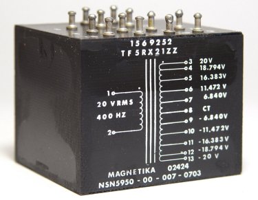
handle and "high voltage" and "high current" exist, but don't ask what they cost ... So, I used the OPA548 and
the output of this power OpAmp drives the primary of a 400 Hz transformer that I found on eBay. Great little gizmo! The size
is small and its weight is small (because of the 400 Hz operating frequency), and it has many taps so that I can select taps
to obtain the desired 26V AC 400 Hz. Keep in mind that at 400 Hz, you need significant less iron to transfer energy from the
primary coil to the secondary, so even at higher power ratings (Watt), a 400 Hz transformer is a lot smaller.
A more detailed description of this design is in the "Center Console -> HSI" page.
 |
 |