| RA81 hard disk drive |
| UDA50 controller |
Direct jumps to:
INTRODUCTION
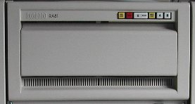 The RA81 is a random-access, moving head (Winchester) fixed disk drive and was introduced in 1982.
It has a non-removable media using a head/disk assembly (HDA) with a capacity of 456 Mbytes.
The RA81 connects to the controller via the Standard Disk Interconnect (SDI) bus. Additional drives can be connected to a
controller to increase the data storage capacity. The RA81 can also be connected in a dual-port arrangement permitting
time-shared access by two controllers.
The RA81 is a self-contained disk drive with built-in cooling system and DC power supply.
An RA81 disk drive subsystem is made up of an SDI controller and one or more disk drives.
Key figures are the following.
- Storage capacity of 456 Mbyte in 16-bit word format (18-bit HDAs do also exist)
- Heat dissipation is 644 Watt nominal
- 17.4 Megabit/sec peak transfer rate
- 28 msec average positioning rate (average seek time)
- 7 msec maximum positioning rate (cylinder to cylinder)
- 50 msec maximum seek (innermost to outermost cylinder, in total 1258 cylinders)
- 8.3 msec average rotational latency, rotational speed is 3600 RPM
The HDA (head/disk assembly) consists of four platters. Seven surfaces are for recording data, the eighth surface has
dedicated servo information for positioning the read/write heads. The HDA can easily be damaged. When you move or transport the drive
you must lock the HDA. This is a fairly simple procedure and is described a bit further down.
The disk drive start-up time is 20 seconds maximum, and the stop time is also 20 seconds maximum. However, there is also a maximum
number of start/stop you can do, which is 6. This means that there is at least 3 minutes between cycles with drive powered up and
ready during one of the 3-minute cycles.
The Standard Disk Interconnect (SDI) bus is a high-level command based interface used to connect to
D|I|G|I|T|A|Ls RA-series drives.
The SDI cables are small and contain four 0.125" coaxial cables with a special connector at the end.
AVAILABLE DOCUMENTION
- RA81 Disk Drive User Guide (EK-0RA81-UG-001)
- RA81 Disk Drive Maintenance Guide (AA-M879B-TC)
- RA80/RA81 disk drive Maintenance Course (EY-4663E-W1-0001)
- RA80/RA81 disk drive Maintenance Course Workbook 2 (EY-4663E-W2-0001)
- RA80/RA81 disk drive Maintenance Course (EY-4663E-W3-0001)
- RA80/RA81 disk drive Maintenance Course (EY-4663E-W4-0001)
- RA80/RA81 disk drive Maintenance Course Student Laboratory Guide Workbook 5 (EY-4663E-W5-0001)
- RA80/RA81 disk drive Maintenance Course (EY-4663E-SG-0001)
- RA80/RA81 disk drive Maintenance Course Error log and diagnostic printout workbook(EY-4663E-WB-0001)
- UDA50 Adapter, UNIBUS disk Field Maintenance Print Set (M7485/M7486)
(MP01331-00 Rev. A and Rev. C)
- UDA50 User Guide (EK-UDA50-UG-002)
- UDA50 Maintenance Guide (AA-M185C-TC)
- UDA50-Q User's Guide (EK-UDA5Q-UG-002 and EK-UDA5Q-UG-003)
- UDA50-Q Service Manual (EK-UDA5Q-SV-002)
GENERAL DRIVE INFORMATION
The RA81 is a real power hog as you can see from the following table. Also, in dimensions and weight the RA81 disk drive is not a baby.
| RA81 drive power information |
|---|
| power source | current requirement | power requirement |
|---|
| 120 Volt / 60 Hz. | 35 Amps peak surge for 4 sec. | starting power 4200 Watt |
| 7.8 Amps rms (running) | running power 644 Watt |
| 220-240 Volt / 50 Hz. | 18 Amps peak surge for 4 sec. | starting power 4320 Watt |
| 3.5 Amps rms (running) | running power 496 Watt |
|
| Drive specifications RA81 |
|---|
| Height | 26.40 cm (10.38") |
| Width | 44.50 cm (17.80") |
| Depth | 67.3 cm (26.50") |
| Weight | 67.1 kg (148 lb) |
|
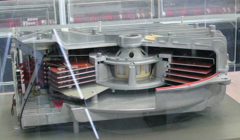
Open model of the RA81 HDA from D|I|G|I|T|A|L European Education Center
HOW TO USE THE RA81 DRIVE
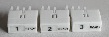 Each RA81 drive has its separate cable connection to the controller. The drive number is set by the
"READY" plug, just as the "READY" plugs on the RL01/RL02 and RK06/RK07 disk drives.
Although the "READY" plugs for the RL01/RL02 numbers are 0 to 3 and the "READY"
plugs for the RK06/RK07 numbers are 0 to 7, the "READY" plugs for the RA8x drive numbers go from 0 to
255! This "READY" plug has eight pins (four on each long side) which represent the binary code 0-255.
A pin still on the "READY" plug represents a logic '0', a pin that is cut off represents a logic '1'.
You can see this clearly in the picture.
Each RA81 drive has its separate cable connection to the controller. The drive number is set by the
"READY" plug, just as the "READY" plugs on the RL01/RL02 and RK06/RK07 disk drives.
Although the "READY" plugs for the RL01/RL02 numbers are 0 to 3 and the "READY"
plugs for the RK06/RK07 numbers are 0 to 7, the "READY" plugs for the RA8x drive numbers go from 0 to
255! This "READY" plug has eight pins (four on each long side) which represent the binary code 0-255.
A pin still on the "READY" plug represents a logic '0', a pin that is cut off represents a logic '1'.
You can see this clearly in the picture.
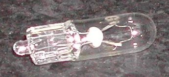
The light bulbs used in the RA81 front panel have number #86. When this number is not telling you anything, the rating for
these bulbs is 6.3 Volt. Note that bulbs used in the RL01/RL02 have number #73, and are 14 Volt.
As you can see from the table "RA81 drive power information", the start-up current of the drive is an issue to think
about when you turn on the system. My RA81 disk drive is connected to the PDP-11/44 and turning on this system with
the key switch is already a big switch-on load on the power line, so it is not advised that this key switch also turns
on the RA81 drive. The rush-in current might blow the power line fuse! An other issue to consider is the rush-in current
if you have more RA8x drives in the system. DIGITAL recognized this problem and all RA8x drives have a so-called
"drive sequence" connection.
 Each RA8x drive has a DRIVE SEQUENCE-IN socket right of the B-port SDI cable (near the edge of the drive)
and a DRIVE SEQUENCE-OUT socket left of the A-port SDI cable at the rear side of the drive. On the first
RA8x drive the DRIVE SEQUENCE-IN socket has a drive sequence connector terminator installed. In this
'terminator' connector are simply two pins shorted. A drive sequence cable goes from the DRIVE SEQUENCE-OUT
socket of the first drive to the DRIVE SEQUENCE-IN socket of the next drive. The last drive in the
chain has no drive sequence connector installed in the DRIVE SEQUENCE-OUT socket.
Each RA8x drive has a DRIVE SEQUENCE-IN socket right of the B-port SDI cable (near the edge of the drive)
and a DRIVE SEQUENCE-OUT socket left of the A-port SDI cable at the rear side of the drive. On the first
RA8x drive the DRIVE SEQUENCE-IN socket has a drive sequence connector terminator installed. In this
'terminator' connector are simply two pins shorted. A drive sequence cable goes from the DRIVE SEQUENCE-OUT
socket of the first drive to the DRIVE SEQUENCE-IN socket of the next drive. The last drive in the
chain has no drive sequence connector installed in the DRIVE SEQUENCE-OUT socket.
When power is applied to all drives, only the first drive will actually spin up.
When the rush-in current is dropped (for this first drive), the second drive can spin up, because the first drive enables the second
drive through the drive sequence connection.
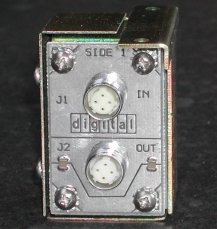
All drive sequence cables have at both ends a male plug, and the RA8x drives have drive sequence IN and OUT female sockets.
To connect 2 cables, for example between 2 cabinets, you need the small box as in the picture at the left. At the rear side are
also 2 sockets.
HOW TO TRANSPORT AN RA81 DRIVE
When you want to move an RA81 drive, you must always lock the HDA. To lock the HDA, do the following steps.
 |
 |
| HDA with lever in locked position |
HDA with lever in unlocked position |
- Open the front/top of the drive.
Across the front of the drive, near the bottom, is a row of vertical ventilation slots.
Behind the slot in the middle is a metal plate. Push this metal plate a little inward with a small screwdriver. This unlocks the
catch mechanism. Now you can swing the entire front and top of the drive up. In the top part are the circuit boards. In the bottom
part is the heavy HDA and the drive motor.
Only a hydraulic damper keeps it open, and since the top part has some weight (...), I use a wooden stick to keep it open.
- Lock the HDA.
The Head/Disk Assembly is the big round thing in the center of the drive. In newer drives the HDA has a grey metal appearance.
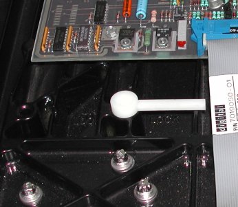
The head locking lever is on top of the HDA, near the left front. This lever (white plastic) can be lifted a little (just a few mm).
When it is lifted you can rotate the lever 180 degrees to go from "unlocked" to the "locked" position. These positions are marked on
the HDA. When you stand in front of the drive, the unlock position is when the lever points to the left (3 'o clock), the lock
position (safe to transport) is set when the lever points to the right (9 'o clock).
 On the righthand side inside the drive is an other handle.
This handle tensions and releases the belt that connects the motor in the back righthand corner to the spindle of the HDA.
This drive belt runs under the HDA and is hard to see without removing it. When this handle is in the forward position, as shown
in the picture, the drive belt is tensioned. There is a metal catch on the side of the box to hold the handle in place. To release
the belt you bend the handle slightly (it has a spring) to get past the catch. Then you can rotate the handle a full 180 degrees,
"pointing" to the rear. In this position the drive belt is not tensioned.
You must release the belt if you want to remove
the HDA. I heard stories that releasing the belt is also a good idea if you plan not to use the drive for some time.
The HDA is mounted on four heavy bolts with large nuts at the top. It sits on thick rubber washers, and can move around
a little bit. Some RA drives have red steel shipping brackets fastened over the bolts to keep the HDA from moving during
transportation. If these red brackets are installed they must be removed and the nuts re-tightened.
The HDA is heavy. You can install and remove the thing on your own, but it is much easier for two persons. If you
need to remove the HDA lock the heads first! When the HDA is removed, set it down on the front. Never put it down on its
bottom, where the pulley is. This will damage the HDA.
The picture on the left is the old type HDA with the black metal housing. This HDA also has the lever in the safe heads locked position.
UNIBUS INTERFACE - UDA50
 The RAxx disk drives interface to the UNIBUS with the UDA50 disk controller, and to the
QBUS with the KDA50.
The RAxx disk drives interface to the UNIBUS with the UDA50 disk controller, and to the
QBUS with the KDA50.
The UDA50 can control up to 4 SDI (Standard Disk Interconnect) disk drives. Each SDI disk drive is connected to the UDA50
with a separate shielded SDI cable. This UNIBUS controller consists of two boards. Each board has a
microprocessor, and for that reason these boards are also called the U and the D processor. The U processor controls the
interface between the UNIBUS and the UDA50 controller. The D processor board controls the interface
between the SDI disk and the UDA50 controller.
There are two versions of the UDA50 controller, simply the "old" and the "new" one. The new UDA50 is an upgrade to improve
the performance, and the most important changes are an increase of the internal RAM from 4k to 16k, the capability to use
larger PROMs, and selectable jumpers for UNIBUS delays to allow the installation of the UDA50 in
various systems. See the table below.
The UDA50 is an MSCP controller. MSCP stands for Mass Storage Control Protocol. MSCP is a communication protocol used with
intelligent mass storage controllers. MSCP hides the device-dependent requirements, such as disk geometry and error recovery,
from the host.
| UDA50 controller |
|---|
| | "old" version | "new" version |
|---|
| ° "U" processor | M7161-YA | M7485 |
| ° "D" processor | M7162 | M8486 |
| Connection cables |
50-pin and 40-pin flat cable to connect the two modules
SDI cable assembly and I/O bulkhead assembly |
| Power consumption | 80 Watts | 83 Watts |
Voltage and current
requirements |
+5 Volt / 11 Amps
+15 Volt / 60 mA
-15 Volt / 2 Amps |
+5 Volt / 12 Amps
+15 Volt / 60 mA
-15 Volt / 1.4 Amps |
| Installation restriction |
Two hex-height UNIBUS SPC slots in BA11-A, BA11-K, or BA11-L box |
Note. The new UDA50 M7485 and M7486 modules are not upward or downward compatible with the old UDA M7161-YA
and M7162 modules. You must replace these modules as a set.
UDA50 INSTALLATION
The two UDA50 modules must be installed in two adjacent SPC slots.
The two modules may be inserted in any order if the NPG jumpers have been removed from both SPC slots. Otherwise make sure that
the module M7161 or M7485 is in the SPC slot without the NPG jumper.
The two modules are interconnected with two 4 inch long flat cables.
See the figure.
UDA50 CONFIGURATION
The UDA50 disk controller has two registers visible in the I/O page.
- Initialize and Polling (IP) register - UNIBUS address octal 772150
- Status and Address (SA) register - UNIBUS address octal 772152
The jumper plug W4/W5 on the "U" processor board sets the UNIBUS address for the IP register. The vector
address (154 octal) for the UDA50 is set by the software. The UNIBUS address selector switches are also
on this "U" processor board.
Click on the picture for a larger image with more info!
The following table shows the UDA50 switch settings, set for address octal 772150.
| UNIBUS address bits |
17 | 16 | 15 |
14 | 13 | 12 |
11 | 10 | 9 |
8 | 7 | 6 |
5 | 4 | 3 |
2 | 1 | 0 |
| octal code |
7 |
7 |
2 |
1 |
5 |
0 |
| binary code |
1 | 1 | 1 |
1 | 1 | 1 |
0 | 1 | 0 |
0 | 0 | 1 |
1 | 0 | 1 |
0 | 0 | 0 |
UDA50 switch setting
|
1 | 1 | 1 |
1 | 1 | S10
ON |
S9
OFF | S8
ON | S7
OFF |
S6
OFF | S5
OFF | S4
ON |
S3
ON | S2
OFF | S1
ON |
W4 | 0 | 0 |
Remark. UNIBUS address bit 2 is set by the jumper plug W4/W5. Only one jumper plug can be installed at
a time. When jumper W4 is installed, bit 2 equals '0'. When jumper W5 is installed, bit 2 equals '1'.
The "U" processor board has an other set of jumpers, W14, to prevent UNIBUS overloading.
These jumpers define the delay on the UNIBUS and depends on the system and its configuration.
| Delay | W14 jumper | System description |
|---|
| 0 µsec | T4 - T5 | - UDA installed
and the only other disk drive
is a RL02 or a RK07 (11/70 system with a RK07 and 1 Mb DMR will not work. The UDA/RK07/DMR11 configuration gives data
late errors from the RK07 regardless of the UDAs jumper settings. Because of this, either a RK07 or a UDA, but not
both can be configured on the 11/70 when a 1 Mb DMR11 is installed).
|
| 6.2 µsec | T5 - T6 |
- UDA installed with multiple DMR11s or DMC11s or DZ11s.
- 11/44 system (or any other PDP-11 with ECC memory) using RM02 or RP04/RP05/RP06 disk drives.
- 11/44 with RL02 or RK07 disk drives.
- 11/24 system (or any other PDP-11 with non-ECC memory) with one or two UDAs installed with other disk controllers and
a DZ11.VAX systems should be treated as an 11/24 for UNIBUS configuration.
- UDA installed on the UNIBUS with one or more real-time data acquisition devices, and real-time data overrun or
underflow is observed. (If underflow or overrun conditions are observed after setting the UDAs jumper to the 6.2 µsec
position, the UDA jumper must be set to the 10 µsec position).
|
| 10 µsec | T5 - T7 |
- 11/44 system with RL02 and RK07 disk drives.
- 11/70 system with a UDA/RL02/DMR11 (1 Mb) mix.
|
There are exceptions to using the UNIBUS delay in preventing overload and the number of UDAs that can be installed
in a system. They are the following.
- The UDA should not be installed in a UNIBUS system which has a bus repeater, because the repeater slows the UNIBUS.
Other devices such as RK07, RM02, and RP04/RP05/RP06 may also experience data late conditions.
- The UDA must be installed after all non-buffered devices on the UNIBUS.
- On PDP-11 systems, there may be no more than 2 UDAs installed on a UNIBUS. However, on VAX systems,
no more than one UDA should be installed on a UNIBUS with non-buffered UNIBUS peripheral devices.
Remark. The old UDA50 M7161 module has the UNIBUS delay jumpers installed starting with revision E.
UDA50 - RAxx DRIVE CONNECTION
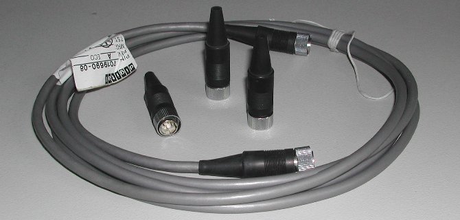
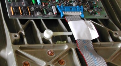
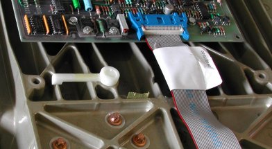
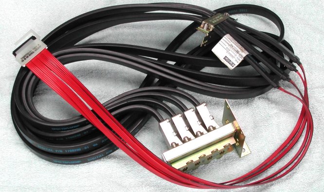 The picture shows the connection cable from the UDA50 (M7162 or M7486) control module (the connector with the 4 red cables)
to the black cables with the typical SDI connectors fitted on the bulkhead. This SDI cable assembly has the part number
70-18455-6K. These cables are shielded and just after the transition from the red to the black stronger cables is a
fixing strip to install this quite heavy cable assembly and ground the (blank) shielding at that point to the chassis of the system.
Each black cable consists internal of 4 coaxial cables! Such a black cable runs from each RAxx drive to the bulkhead inside that
cabinet that houses the drive.
The picture shows the connection cable from the UDA50 (M7162 or M7486) control module (the connector with the 4 red cables)
to the black cables with the typical SDI connectors fitted on the bulkhead. This SDI cable assembly has the part number
70-18455-6K. These cables are shielded and just after the transition from the red to the black stronger cables is a
fixing strip to install this quite heavy cable assembly and ground the (blank) shielding at that point to the chassis of the system.
Each black cable consists internal of 4 coaxial cables! Such a black cable runs from each RAxx drive to the bulkhead inside that
cabinet that houses the drive.
So, you need a third cable (either rectangular shaped or round) to connect the system and the cabinet.
Remark. The total count of the cables between the UDA controller and the drive must be odd !
|
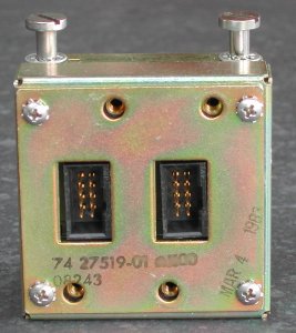
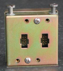
As SDI cables have a female connector at both ends of the cable, you need a little box to connect
two cables.The picture at the left shows the front side, and the picture on the right shows the rear side of such a box.
The box has connectors for 2 sets of cables, to support the connection to the "A" and the "B" controller.
The two long screws are used to install the connection box on a bracket inside a cabinet.
|
|
CONTROLLER DIAGNOSTICS
The UDA50 has resident diagnostics which is started when power is applied to the controller. The CPU should be halted
during this test. The four LED indicators on each UDA50 module should display a cycling pattern in the LEDs. The
cycling pattern indicates the completion of a successful UDA50 diagnostic test. The LEDs are at the front edge of
the modules.
|
|
| UDA50 modules LED error indicators and symptom codes |
|---|
M7161 / M7485
8 4 2 1 |
M7162 / M7486
8 4 2 1 |
Error symptoms | Most likely failure |
|---|

 |
x x x x |
undefined |
undefined |
|
|
|
microcode stuck in init step 2 |
M7161 / M7485 or software |
|
|
|
microcode stuck in init step 3 |
M7161 / M7485 or software |
|
|
|
microcode stuck in init step 4 or UNIBUS timeout error |
M7161 / M7485 or host inactive |
 |
|
test complete (bit 1 blinks) |
no problem |
x x x x |
x x x x
|
undefined |
undefined |
x x x x |
x x x x
|
undefined |
undefined |
|
|
|
wrap bit 14 set in SA register |
M7161 / M7485 or software |
|
|
board one error |
M7161 / M7485 |
|
|
board two error |
M7162 / M7486 |
x x x x |
x x x x
|
undefined |
undefined |
x x x x |
x x x x
|
ROM parity error |
M7161 / M7485 |
x x x x |
x x x x
|
RAM parity error |
M7162 / M7486 |
x x x x |
x x x x
|
RAM or ROM parity error |
M7161 / M7485 or M7162 / M7486 |
|
|
|
sequencer error |
M7161 / M7485 |
cycling
pattern |
cycling
pattern |
UDA responds to host if cycling pattern lasts less than 2 seconds after host sends step 1 data |
no problem |
| UDA does not responds to host if cycling pattern lasts more than 2 seconds after host sends step 1 data |
M7161 / M7485 |
The RAxx/UDA50 disk subsystem has the following diagnostics mentioned in the RA81 User Guide manual.
• CZUDCC0
• CZUDEC0 | |
- UDA and disk drive diagnostics (old, no longer used)
- UDA disk formatter |
In a KDA50 manual the following XXDP programs are mentioned. They probably also work for a UDA50.
• CZUDH
• CZUDI
• CZUDJ
• CZUDK
• CZUDL
• CZUDM | | |
- UDA50/KDA50 Disk drive formatter
- Disk Exerciser test
- Subsystem exerciser test
- KDA50 Disk drive formatter
- Bad Block replacement Utility
- Disk Resident Error Log Utility |
Besides the XXDP diagnostics, the controller inside the RA81 drive has some "self" diagnostics.
- front panel button lights
First of all, the front panel button lights give an error identification error code when the "FAULT" lamp is lit.
Push the FAULT button in to see the error code. Make sure that all the light bulbs are ok ...
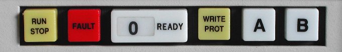
| RA81 front panel error code indications |
|---|
RUN
STOP | FAULT | READY | WRITE
PROT | A | B | error description |
|---|
| - | on | - | - | - | on | spin error |
| - | on | - | - | on | - | microprocessor fault |
| - | on | - | - | on | on | SDI error |
| - | on | - | on | - | - | master/slave error |
| - | on | - | on | - | on | servo fine positioning |
| - | on | - | on | on | - | servo coarse positioning |
| - | on | - | on | on | on | spindle motor interlock error |
| - | on | on | - | - | - | servo er HDA overtemp error |
| - | on | on | - | - | on | R/W unsafe error |
| - | on | on | - | on | - | R/W command error |
| - | on | on | - | on | on | servo/HDA interlock error |
| - | on | on | on | - | - | servo/microprocessor interlock error |
| - | on | on | on | - | on | read/write microprocessor interlock error |
| - | on | on | on | on | - | control panel/microprocessor interlock error |
| - | on | on | on | on | on | personality/microprocessor interlock error |
| on | on | - | - | - | - | index error |
| on | on | - | - | - | on | write and bad embedded data error |
| on | on | - | - | on | - | drive disabled by DD bit |
| on | on | - | - | on | on | write enable and write protect asserted error |
| on | on | - | on | - | - | servo diagnostic test error |
| on | on | - | on | - | on | R/W diagnostic test error |
| on | on | - | on | on | - | diagnostic idle loop test error |
| on | - | on | on | on | on | DC low ** note: FAULT light off ** |
| on | on | on | on | on | on | microprocessor hardcore test error |
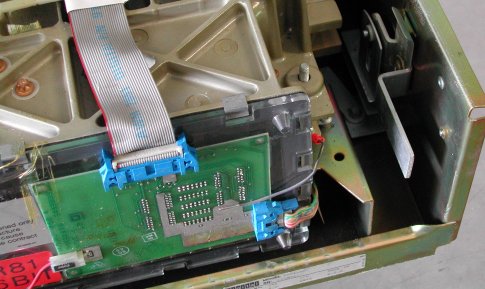
- diagnostic terminal RS-232 port connector
Inside the RA81 drive is a DB-25 connector. This connector is deep inside the drive.
To access this connector you must open the
top lid and rotate the logic boards. The connector is on the right hand side.
You can connect a VT220 to it for example. A simple 3-wire cable is enough.
Wire two female DB25 connectors with #2 -» #3, #3 -» #2 and #7 -» #7.
Set the terminal to 300 Baud, 7 databits, no parity.
When everything is powered-up, enter a few carriage returns (CR) or control-C's. You get a ">>>" prompt.
Make sure that the RUN, the A and the B button is not pushed in. Enter at the prompt "RUN DIAG" to exercise the drive.
If it passes the diagnostics, start the drive and execute an other "RUN DIAG".
RA81 BOOTSTRAP DATA
I do not have any bootstrap code for the RA81.
Does anybody know if there exists a bootstrap you can toggle in or load with the monitor?
If you have, please mail it to me. I will try it on my PDP-11/44 to which the RA81 is connected, and list it here, of course.
A boot PROM exists for MSCP disk drives (like the RA81 or RA60), its number is 23-767A9. You must install this boot PROM
on the M9312 Bootstrap/terminator module or use the PROM sockets in an 11/24 or 11/44 CPU. For more information on the M9312
module, see the PDP-11/34A folder, and use the link
'CPU information -» options -» bootstrap'
(and loose the navigation overview) or use the navigation tree at the left side.
Here are some more links where you can find more information.