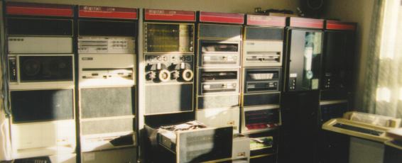
 This page shows my PDP-11/35 system that I have at home. It is housed in six H960 industrial 19" cabinets
(from DIGITAL). One cabinet contains the actual PDP-11/35 rack. The other cabinets contain the peripheral
devices like tape drives and disk units.
This page shows my PDP-11/35 system that I have at home. It is housed in six H960 industrial 19" cabinets
(from DIGITAL). One cabinet contains the actual PDP-11/35 rack. The other cabinets contain the peripheral
devices like tape drives and disk units.
The PDP-11/35 is the OEM version of the PDP-11/40. Hardware-wise the central processors are identical.
DIGITAL introduced the PDP-11/40 in 1972. The PDP-11/40 offers approximately twice the processing power of the
earlier PDP-11/20. A floating point package was offered as an option, making the cost slightly lower than the
PDP-11/20.
(The PDP-11/20 was the first 16-bit processor, April 1970).
This system is my 'favourite' system, and only fellow-collectors can understand what I mean to say.
Since the original 11/35 rack (21" version) can have backplanes to support up to 38 slots (for printed
circuit boards) and my system needs more, one of the other cabinets houses an expansion box. This is another
unit which supports up to 38 slots and has its own power-supply. The UNIBUS is brought from the last slot
in the 11/35 rack to the first slot in the expansion box via a 15-foot BC11 cable.
Jumps within this page are the following:
GENERAL SYSTEM INFORMATION
|
- System history
-
This PDP-11/35 has been built in 1972, and has been used for the control of traffic lights in a city.
The PDP's are mainly used for process control because of their reliabilty. There are stories of
machines which have been running without any problem for over 10 years!
- System description
-
My PDP-11/35 consists of the basic KD11-A 11/40 Central Processing Unit, and is equiped with all PDP-11/40
available processor options. The processor boards and the options are all described on the page CPU
information. This is a subfolder of the PDP-11/35 folder. The PDP-11/40 processor options are :
- KW11-L line time clock
- KT11-D memory management
- KJ11-A stack limit register (required by KT11-D)
- KE11-E Extended Instruction Set, EIS
- KE11-F Floating Instruction Set, FIS
The system is completed with the following peripherals :
- disk storage units
- magnetic tape storage units
- communication devices and interfaces
- line printer/console DECwriter II
- monitor console VT55-FB with built-in printer
- DEUNA or DELUA Ethernet network interface
|
|
When you click on the link you can read more about the specific peripheral device. All peripherals that I have
are also described in the 'subfolder' peripherals, on which you can click in the left-hand navigation
section.
To return to this location, click on the text 'PDP-11/35' after the first subfolder.
I hope to add an original DIGITAL paper tape reader/punch unit (PC11), and a bootselector switch (H324-UA)
to this system in the future. So, if you have one of these things, and you want to get rid of it (...),
please contact me.
Back to top
11/35 SYSTEM CONSOLE
The front panel of the PDP-11/35 has a few more buttons, switches and lights than the average Personal
Computer, as you can see. I guess this is what makes these old systems 'beautiful', compared with a modern PC.
The console has 16 LEDs for display of data, 18 LEDs for the display of an address and 6 LEDs to indicate the
CPU status: RUN, PROC, BUS, CONSOLE, USER and VIRTUAL. The meaning of all these lights is explained a bit further.
From left to right there are 18 switches to set up an address or to load data, 3 buttons (momentary push down)
for loading and examining an address and to continue the CPU, a switch to halt the CPU and one button (momentary
push up) to deposit data into a memory location.
| PDP-11/35 and PDP-11/40 console indicators |
|---|
ADDRESS
Register |
displays the address of data just examined or deposited. During a programmed HALT or WAIT instruction,
the display shows the next instruction address.
|
DATA
Register |
displays data just examined or deposited. During HALT, general register R0 contents are displayed. During
Single Instruction operation, the Processor Status word (PS) is displayed.
|
| RUN |
lights when the processor clock is running. It is off when the processor is waiting for an asynchronous
peripheral data response or during a RESET instruction. It is on during a WAIT or HALT instruction.
|
| PROCESSOR |
lights when the processor has control of the bus.
|
| BUS |
lights when the UNIBUS is used.
|
| CONSOLE |
lights when in console mode (manual operation). Machine is stopped and is not executing the stored program.
|
| USER |
lights when the CPU is executing program instructions in User mode.
|
| VIRTUAL |
lights when the ADDRESS Register display shows the 16-bit Virtual Address.
|
| PDP-11/35 and PDP-11/40 console switches &
toggles |
|---|
SWITCH
Register |
used to manually load data or an address into the processor.
Switch position "up" = '1' ,and "down" = '0'.
|
| LOAD ADRS |
transfers contents of the Switch Register to the Bus Address register. The resulting Bus Address is
displayed in the ADDRESS Register, and provides an address for EXAM, DEP, and START. The LOAD address is not
modified during program execution. To restart a program at the previous Start Location, the START switch is activated.
|
| EXAM |
causes the contents of the location specified by the Bus Register to be displayed in the DATA Register.
If the EXAM switch is depressed again, the contents of the next sequential word location are displayed (Bus Address
is incremented automatically). If an odd address is specified, the next lower even address word will be displayed.
If a non-existent memory address is specified, no UNIBUS operation will be completed, and contents of the Switch
Register address (777570) will be displayed in the DATA Register.
|
| CONT |
causes the processor to continue operation from the point at which it has stopped. The switch has no effect
when the CPU is in the RUN state. If the program has stopped, this switch provides a restart without a System Reset.
|
ENABLE
HALT |
ENABLE: allows the CPU to perform normal operations under program control.
HALT: causes the CPU to stop. Depressing the CONT switch will now cause execution of a single instruction.
|
| START |
if the CPU is in the RUN state, the START switch has no effect. If the program had stopped, depressing
the START switch causes a System Reset signal to occur; the program will then continue only if the ENABLE/HALT
switch is in ENABLE.
|
| DEP |
deposits contents of the Switch Register into the location specified by the Bus Address. If the DEP switch
is raised again, the Switch Register contents (which were probably modified) are located into the next word
location (Bus Address is incremented automatically). If an odd address is specified, the next lower even address
word will be used. If a non-existent memory address is specified, no UNIBUS operation will be completed, and contents
of the Switch Register address (777570) will be displayed in the DATA Register.
|
Back to top
THIS 11/35 SYSTEM CONFIGURATION
This system is housed in two BA11-F chassis. The BA11-F chassis can accomodate up to 38 slots, a mix of 4-slot
and 9-slot backplanes. The KD11-A processor has its own dedicated 9-slot backplane, so that leaves room in the
first chassis for more additional 9-slot backplanes, or a mix with 4-slot backplanes.
Here is a diagram of how the system BA11-F chassis and the expansion BA11-F chassis are 'loaded'.
A backplane that supports a complete function is called a system unit. The DD11-B and the DD11-DK are examples
of general purpose system units. They can have several boards with different functions in its backplane.
Every system unit has an UNIBUS-in and a UNIBUS-out slot. The 'out'-section connects to the 'in'-section of
the next system unit with a "module bridge" connector.
The KD11-A system unit has 9 slots which are all dedicated to the processor and its options. As this system
unit is the first in a PDP-11/40 (or 11/35), there is no UNIBUS-in. That is actually on one of the processor
boards itself. The last (9th) slot of this system unit has the UNIBUS-out and a so-called SPC slot. SPC stands
for 'Small Peripheral Connection'. This SPC-slot commonly holds the interface card to connect the system console.
The MF11-UP is also a 9 slot dedicated backplane, configured for one option. The MF11 is a system unit which
supports two boards each holding 16k x 18 bit core memory mats. The other slots contain boards to control the core
memory (read and write operations) and for the '-UP' version the parity control.
The DD11-B is a 4 slot general purpose back plane. In my configuration this system unit houses the RX211
(M8256) interface for the RX02 floppy drives, the RL11 (M7762) interface for the RL drives, the KW11-P (M7228)
programmable timer option, and the M792 board, which is a 32 word 'ROM' build by adding/removing diodes.
The DJ11 is a 4 slot dedicated system unit for the support of 16 multiplexed serial communication lines.
The RK11-D is a 4 slot dedicated system unit for the support of up to eight RK05 disk drives.
The RH11-AB is a 9 slot dedicated system unit that houses the MASSBUS interface. MASSBUS is a parallel
interface bus to which you can connect MASSBUS disk drives and MASSBUS tape drives. In my configuration I need the
MASSBUS interface to connect the TE16 tape drives.
The last backplane is the DD11-DK. This is a 9 slot general purpose backplane, and it holds the Ethernet
network interface and the bootstrap terminator. Note that the terminator must go in the UNIBUS-out, and not in the
last used slot of the backplane, for example slot 3. In this case, the terminator must go in slot 9. All the not
used slots must have a grant-continuity card to continue the UNIBUS. If one slot is left open, the system will hang.
All the system units are interconnected with a M920 module bridge. The interconnection between the two BA-11
boxen is done with a BC11-15 cable.